
Sophia Electric EL34 Schematic
The schematic in question likely involves a basic amplifier circuit, which may include components such as resistors, capacitors, transistors, and possibly operational amplifiers (op-amps). The primary function of an amplifier is to increase the amplitude of a signal, which can be an audio signal, radio frequency, or any other type of electronic signal.
In a typical amplifier circuit, the input signal is fed into the base or gate of a transistor or op-amp, which then controls the larger current flowing through the collector or drain, effectively amplifying the input signal. Resistors are commonly used for biasing the transistors, ensuring they operate within their active region, while capacitors may be employed for coupling and decoupling signals, as well as for filtering purposes.
Power supply considerations are also critical in amplifier design, as the circuit needs to be powered adequately to handle the required output levels without distortion. The output stage may include additional components to drive speakers or other loads, ensuring that the amplified signal is delivered effectively.
Understanding the role of each component in the circuit and how they interact is essential for mastering amplifier design. This knowledge can be further enhanced by experimenting with different configurations, such as inverting and non-inverting amplifier setups, to observe how changes affect performance parameters like gain, bandwidth, and linearity.I have finally worked out this schematic as an exercise to learn about amps. There are a number of things i am not so sure about and would appreciate.. 🔗 External reference
Related Circuits
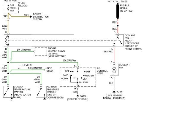
The following page outlines detailed information and the schematic of the 1985 Pontiac Fiero Wiring Diagram and Electrical System. The electrical system consists of: The 1985 Pontiac Fiero features a complex electrical system designed to support various components and functionalities...
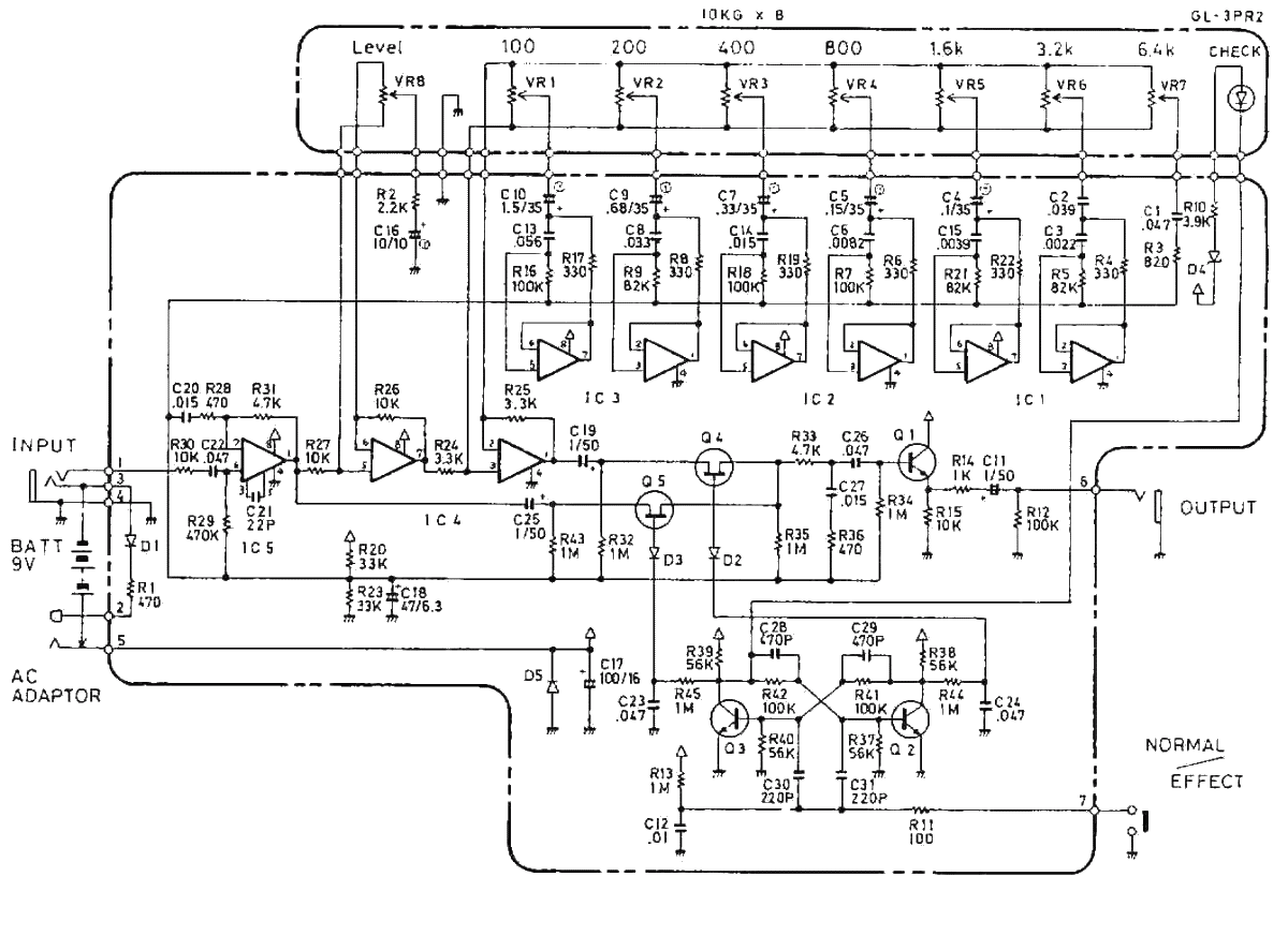
The Boss GE-7 Equalizer pedal modifies the harmonic content of an instrument across 7 distinct frequency bands, spanning from 100Hz to 6.4kHz, with a boost or cut of up to 15dB for each band. An additional Level control knob...

In today's environment, where viruses and other threats from the Internet are prevalent, it is essential to ensure that a personal computer (PC) remains secure from infections. This circuit was designed to facilitate the installation of multiple hard disks...
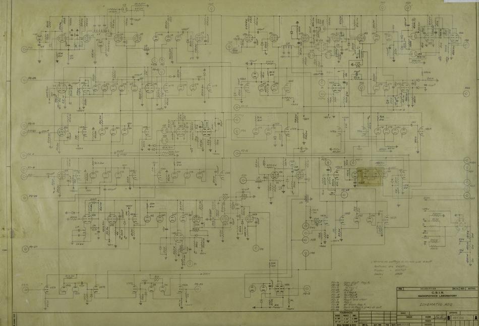
A schematic diagram illustrates the detailed connections between all components in a circuit. These diagrams are utilized for circuit construction and subsequent testing. In the case of CSIRAC, the primary components included vacuum tubes (valves), capacitors, and resistors. Schematic diagrams...
Is there a recommended schematic for the 211 / VT4C similar to the Air Tight ATM-211? It would be preferable if it does not include an interstage transformer and 6SN7. The request pertains to the design of an audio amplifier...
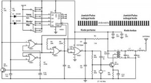
The following circuit illustrates a schematic diagram for a remote control toy car. Features: it does not affect the performance of the original design. The remote control toy car schematic circuit diagram typically consists of several key components that work...