
Boss GE-7 Equalizer guitar pedal schematic diagram

The Boss GE-7 Equalizer pedal features a versatile design that allows musicians to shape their sound precisely. Each of the seven frequency bands is carefully selected to cover the critical range of human hearing, ensuring that users can enhance or attenuate specific tonal qualities of their instrument. The frequency bands include: 100Hz, 200Hz, 400Hz, 800Hz, 1.6kHz, 3.2kHz, and 6.4kHz, enabling fine-tuning of bass, midrange, and treble frequencies.
The ability to boost or cut each band by 15dB provides significant control over the tonal characteristics of the instrument. This feature is particularly useful for live performances or studio recordings, where achieving the desired sound is essential. The Level control knob adds an extra layer of functionality, allowing the player to adjust the overall output level of the pedal. This can be particularly beneficial when switching between different sound settings, ensuring a consistent volume level regardless of the EQ adjustments made.
The pedal's design typically includes LED indicators to show when the effect is engaged, and the rugged construction ensures durability in various performance environments. The GE-7 is compatible with a standard 9V power supply, making it easy to integrate into existing pedalboards. Overall, the Boss GE-7 Equalizer pedal is a powerful tool for musicians seeking to refine their sound, offering both flexibility and precision in tonal adjustment.The Boss GE-7 Equalizer pedal adjusts the harmonic contents of an instrument in 7 separate bands ranging from 100Hz to 6. 4kHz, with a boost/cut 15dB per band. The additional Level control knob helps you to set a different volume for normal and effect sound (or to use the pedal only as a gain booster).
🔗 External reference
Related Circuits
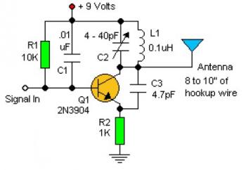
Experimenting with the size of the coil and the number of turns can influence the frequency and signal output of the oscillator. The signal can be received using a standard FM radio receiver. The input signal should be coupled...
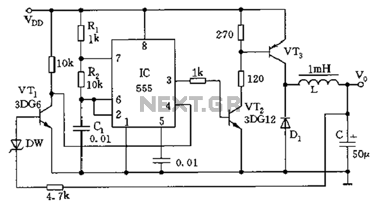
The circuit consists of a 555 timer configured as an astable multivibrator along with resistors R1 and R2 and capacitor C1. It generates an oscillation frequency of approximately 10 kHz with a duty cycle close to 50%. Transistors VT2...
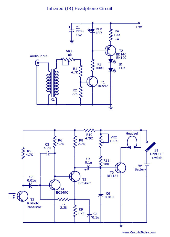
This document outlines a simple infrared (IR) headphone circuit designed for listening to television or radio without disturbing others. The IR headset is a preferable option for beginners compared to FM headsets due to its desirable sound quality that...
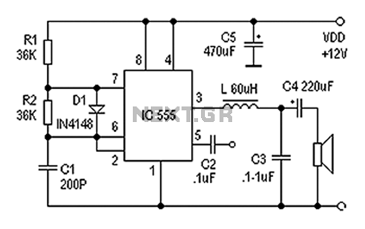
Also known as a digital amplifier, the Class-D amplifier is characterized by its compact size and high efficiency. This circuit utilizes a 555 timer IC to create a Class D amplifier. The 555 timer operates as a controllable multivibrator,...
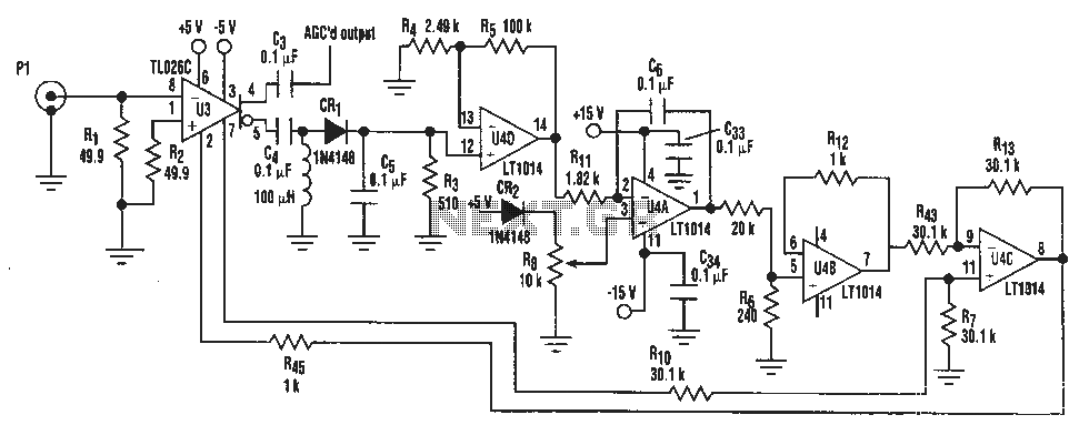
A simple IF AGC signal with a wide dynamic range and excellent linearity characteristics may be composed of two chips: the TL026C T1 voltage control amplifier IC and the LT1014 (or any other similar basic quad op amp device). The...
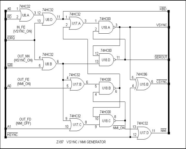
The ZX97 was developed as a discrete replica of the ZX81, which served as the first personal computer for millions. However, the ZX97 evolved into more than just a simple copy. While maintaining backward compatibility with the ZX81, it...