
211 VT-4C Good Simple SE Schematic
The request pertains to the design of an audio amplifier circuit utilizing the 211 (VT4C) vacuum tube, with a specific interest in a configuration akin to the Air Tight ATM-211 model. The inquiry emphasizes the desire to avoid the complexity of an interstage transformer and the use of the 6SN7 tube, which is commonly employed in many high-fidelity audio applications for its excellent linearity and low noise characteristics.
In designing a schematic for a 211-based amplifier, it is essential to focus on the tube's operating characteristics, including its high voltage and current requirements. The 211 tube can be configured in a single-ended or push-pull arrangement, but for simplicity and to adhere to the request, a single-ended design may be more suitable.
The amplifier circuit should include a power supply section capable of providing the necessary high voltage, typically around 300-400 volts, along with a separate filament supply for the 211 tube, which usually requires 5 volts at a few amps. The input stage could utilize a high-gain driver tube that does not include the 6SN7, such as a 12AX7 or a 6SL7, which can provide adequate signal amplification while maintaining fidelity.
Coupling capacitors will be necessary to block DC while allowing AC signals to pass through, ensuring that the audio signal is not distorted by the DC bias of the tubes. Output transformers are also critical in this design, as they convert the high-voltage signal from the tube to a lower voltage suitable for driving speakers. Selecting a high-quality output transformer designed for 211 tubes will significantly impact the overall sound quality.
Feedback could be implemented in the circuit to enhance linearity and reduce distortion, although the specific method of feedback should be chosen carefully to avoid introducing unwanted phase shifts.
Overall, the schematic should be meticulously laid out, ensuring that all components are rated appropriately for the voltages and currents they will encounter. Proper grounding and layout practices will also be critical to minimize noise and maintain signal integrity throughout the amplifier's operation.Hi, does somebody have a good 211 / VT4C schematic like Air Tight ATM-211 to recommend ? If it`s possible without interstage transformer and 6SN7.. 🔗 External reference
Related Circuits
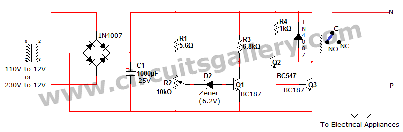
Voltage fluctuation is a significant concern in residential settings. For various reasons, the supply voltage may exceed 110V or 230V. This excessive voltage can potentially damage household electrical devices. An effective solution for electrical protection is the implementation of...
The original coil that came with the Heathkit project was preassembled at the factory. It had a diameter of around 15 cm (6 inches). A larger (30 cm, 12 inches) coil can be made using the following data. The design...
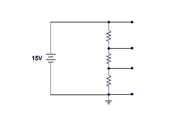
Ground serves as a reference point for the voltage divider, with each successive point above ground indicating the voltage drop across the circuit. For example, with a 15-volt input and 5K ohm resistors, the voltage taps would measure 5,...
This cable TV amplifier circuit is an RF amplifier designed for quick installation between two coaxial cables. Both the input and output impedances are compatible with 75-ohm cables. The main amplifier is the T1 transistor, while T2 functions as...
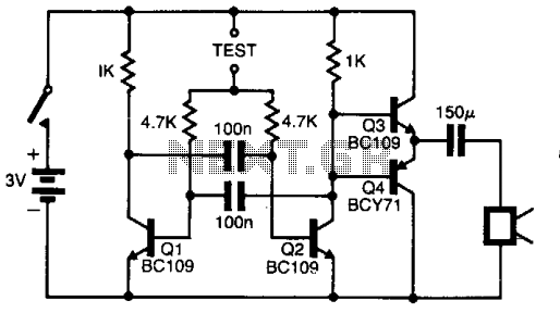
The pitch of the tone is dependent upon the resistance under test. The tester will respond to resistance of hundreds of kilohms, yet it is possible to distinguish differences of just a few tens of ohms in low-resistance circuits....
This simple circuit helps detect RF radiation leaking from transmitters, improper joints, broken cables, or equipment with inadequate RF shielding. This circuit is designed to identify and measure radio frequency (RF) radiation emissions, which can indicate issues such as faulty...
Warning: include(partials/cookie-banner.php): Failed to open stream: Permission denied in /var/www/html/nextgr/view-circuit.php on line 713
Warning: include(): Failed opening 'partials/cookie-banner.php' for inclusion (include_path='.:/usr/share/php') in /var/www/html/nextgr/view-circuit.php on line 713