
sound capture

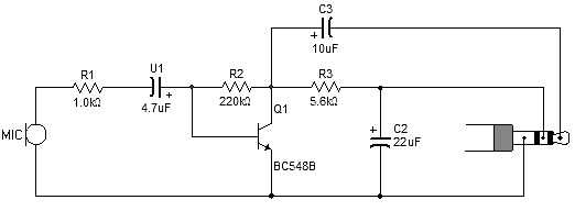
The microphone amplifying circuit described operates effectively within the specified voltage range of +5V to +12V, ensuring compatibility with various power supply configurations. The use of an electret microphone is advantageous due to its low power consumption and adequate sensitivity for sound capture applications. The biasing arrangement provided by resistors R7 and R8 ensures that the microphone operates within its optimal range, while capacitor C2 effectively filters out any noise present in the power supply, enhancing the overall signal quality.
The first stage of amplification utilizes an inverting operational amplifier configuration, which is common in audio applications due to its ability to amplify weak signals effectively. The gain is adjustable through resistors R3 and R4, allowing for flexibility based on application requirements. The implementation of a virtual ground at half the supply voltage is a critical design choice, as it centers the output signal around a reference level, facilitating more straightforward processing in subsequent stages.
The second amplification stage mirrors the design of the first, reinforcing the signal further. The decision to use two stages rather than a single high-gain stage is a strategic choice to maintain stability and bandwidth, crucial for high-frequency applications. The overall design prioritizes stability and performance, ensuring that the amplifier can handle the demands of various sound analysis tasks without introducing distortion or oscillation.
In summary, this microphone amplifying circuit design is a robust solution for sound analysis, providing adjustable gain, noise filtering, and stability across a range of operating conditions. The careful consideration of component values and configurations ensures that the circuit can perform effectively in real-world applications.After some new experiments on sound analysis, I used a different design for the microphone amplifying section, that I am happy to share with you (From the statistics of Arduinoos, I know that sound capture is a topic of major interest for many of you). The whole circuit is supplied with a clean +5 to +12V, filtered by C5. The microphone (electret t ype) is biased through R7, R8, using a filtering capacitor C2 for removing some power supply noise. The active pin of the micro phone is connected to the first stage of an inverting amplifier (IC2B) via a decoupling capacitor which stops the DC component of the signal and all the AC component to go through. The gain of this amplifier is set by R3 and R4, with G=R3/R4. The non inverting input of the amplifier is set to avirtualground at half the value of VCC (typcally 5/2=2.
5V), so that the signal at rest is about half VCC and swings around this value. Halving VCC is performed by the divider bridge R1/R2, stabilized by C3 and C4. Lacking to install thesecapacitors may lead to an unstable output. The output of this stage is available at pin 7 of IC2B. Someapplicationsmay require an even higher gain, which is achieved by a second amplifying stage. This second stage uses exactly the same design than for the first stage; its gain is set by R5 and R6 [erratic spot on R6 and GND: do not connect]. It shares the same virtual ground as for the first stage. The total gain of the amplifier is the product of the gains from the two stages. BTW, why would we use two stages It is very important not to violate the bandwidth limit of the op amp at the highest frequency seenby the circuit.
Practical circuits can include gains of 100, but higher gains could causethe circuit to oscillate unless special care is taken during PC board layout. It is better to cascadetwo or more equal-gain stages than to attempt high gain in a single stage. 🔗 External reference
Related Circuits
Most sound card microphone inputs require a minimum signal level of at least 10 millivolts, but some older 8-bit cards need as much as 100 millivolts. The typical impedance of the PC sound card microphone input is in the...
Sound effects generators trying to imitate rain sound or sea surf are well known to hobbyists from many years: their purpose is to induce relaxation and sleep or to help in concentration and study. The sound generated is restrained...
The circuit below demonstrates how to construct a DAQ_LITE device, accompanied by an image of the finished PCB board. It is important to note that the 80mA fuse depicted in the image and the nearby protection diode are recommended...
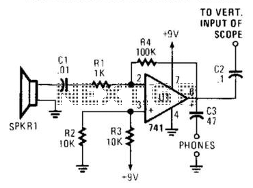
The receiver is an audio amplifier connected to SPKR1, a piezo speaker utilized as a microphone. An oscilloscope or headphones can serve as a detector. The oscilloscope can be triggered horizontally by the transmitted acoustic pulse, while the vertical...
This sound frequency meter circuit is simple to build and can be constructed in a portable format. It can measure frequencies with a minimum level of 10 mV. The sound frequency meter circuit is designed to provide an effective and...
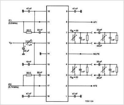
The TDA3567 is a monolithic integrated decoder designed for the NTSC color television standards. It incorporates all the necessary functions for the demodulation of NTSC signals. Additionally, it features a luminance amplifier and an RGB matrix amplifier. These amplifiers...