
Sound Level Indicator
The circuit design effectively combines audio signal processing with visual output, making it an ideal solution for sound level monitoring applications. The LM3915 IC is specifically designed to display analog signals, and its ability to drive multiple LEDs simultaneously allows for a clear visual representation of sound intensity. The automatic gain control mechanism is crucial for maintaining consistent performance across a wide range of input sound levels, ensuring that both quiet and loud sounds are accurately represented.
The choice of a single-supply op-amp for the rectifier driver stage simplifies the power supply requirements and enhances the overall efficiency of the circuit. The inclusion of transistors for voltage reference and automatic gain control adds a level of sophistication to the design, allowing for real-time adjustments in sensitivity based on the input signal. The use of a voltage divider to set the reference voltage for the resistor ladder is a practical approach that enables fine-tuning of the sensitivity threshold.
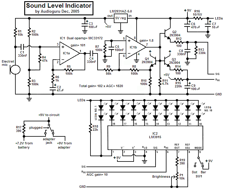
The portable power solution using a rechargeable battery, combined with the trickle charging feature from an AC-DC adapter, enhances the usability of the project in various environments. This design is suitable for applications such as sound level meters, audio equipment diagnostics, and educational demonstrations in acoustics. Overall, this project exemplifies a well-thought-out integration of electronic components to achieve a specific functional objective while maintaining user-friendly features.This project uses an LM3915 bar-graph IC driving two sets of ten LEDs for a 30dB range. The circuit is unique because it has an additional range of 20dB provided by an automatic gain control to allow it to be very sensitive to low sound levels but it increases its range 20dB for loud sounds. The LEDs are operating at 26mA each with the brightness control at maximum, which is very bright. The circuit has a switch to select the modes of operation: a moving dot of light, or a bar with a changing length. My prototype has a little 9V Ni-Cad rechargeable battery in it to be portable and the battery is trickle-charged when the project is powered by a 9V AC-DC adapter.
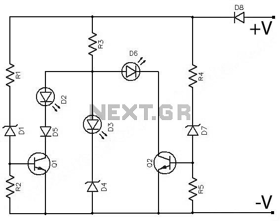
3) The 2nd opamp stage is a single-supply opamp which works fine with its inputs and output at ground and is used as a rectifier driver with a gain of 1. 8. It is biased at ground. Since it is inverting, when its input swings negative, its output swings positive. a) Q1 is inside the negative feedback loop of the 2nd opamp as a voltage reference for the other two transistors.
Hopefully the transistors match each other. c) Q3 transistor is the automatic gain control. It is also a peak detector but has slower charge and discharge times. It drives the comparators` resistor ladder in the LM3915 to determine how sensitive it is. R15 from +5V is in a voltage divider with the ladder`s total resistance of about 25k and provides the top of the ladder with about +0. 51V when there is a very low sound level detected. Loud sounds cause Q3 to drive the top of the ladder to 5. 1V for reduced sensitivity. 5) The LM3915 regulates the current for the LEDs so they don`t need current-limiting resistors. In the bar mode with all LEDs lit then the LM3915 gets hot so the 10 ohm/1W resistor R16 shares the heat.
🔗 External reference
Related Circuits
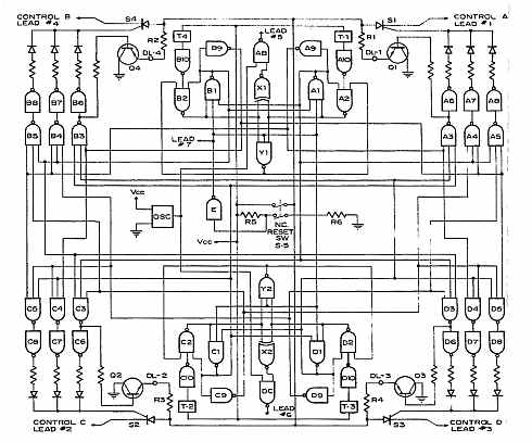
A sound origin direction indicator features a flat square shape with four sound transducer/amplifier units positioned at each corner. It includes four rows of solid-state lamps extending from the center to the corners and an electronic system integrated with...
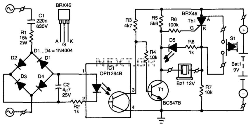
When the mains voltage is present at the input terminals, the transistor in the optocoupler is activated, T1 is off, and the silicon-controlled rectifier (SCR) Th1 is in the conducting state. As a result, both terminals of the piezoelectric...

The headlights of a 2001 Chevy S10 sometimes function and sometimes do not, along with the dashboard indicator light. All other lights are operational. The headlight switch, fuse, and relay have been replaced, and the headlight bulbs have been...
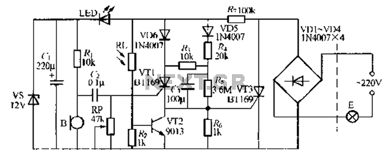
A relatively simple circuit for controlling a stair walkway light with a delay feature. The circuit has a drawback in that the voice activation is somewhat less sensitive, making it sometimes difficult to trigger with general conversation. However, it...
Often, outdoor audio or video recordings suffer from poor quality when the battery is low. If the battery voltage drops below 9V for a 12V recorder, the playback output will be compromised due to variations in the power supply. To...
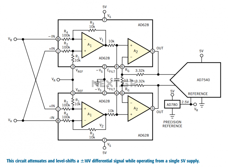
Designers who build equipment for the industrial market share a widespread problem. At one extreme, they must build equipment that supports ±10V bipolar voltages, often riding on a high common-mode level, a requirement enforced by 30 years of legacy...