
sound origin direction finder

The sound origin direction indicator (SODI) is engineered to function through a combination of sound transduction and visual indication. The core of the device consists of four sound transducer/amplifier units (T-1, T-2, T-3, T-4) strategically positioned at the corners of the square housing. Each transducer is sensitive to sound waves, converting acoustic signals into electrical signals for processing. The electronic system then analyzes the timing of the signal received by each transducer, determining the direction of the incoming sound based on which transducer is activated first.
The rows of solid-state lamps (R-1, R-2, R-3, R-4) are critical for visual feedback, providing real-time indication of sound direction. Each row contains 90 lamps, with the last lamp in each row serving as a quadrant indicator (DL-1, DL-2, DL-3, DL-4). The arrangement allows for a clear visual representation of the sound source's direction, as the lamps will illuminate sequentially towards the activated transducer. The separation of the quadrant indicating lamps from the other lamps helps to provide a distinct signal when the sound source is located at the boundary between quadrants.
The device's design ensures portability and ease of use, making it suitable for various applications, including outdoor activities, search and rescue operations, and sound localization research. Its robustness against echoes and the need for repetitive sounds enhances its reliability in real-world scenarios. The SODI's ability to operate within a full 360-degree field makes it versatile, while its potential for modification allows customization based on specific user requirements. Overall, the SODI represents a significant advancement in sound localization technology, combining efficient sound detection with intuitive visual feedback.A sound origin direction indicator comprising a flat square-shaped form having four sound transducer/amplifier units mounted at its four corners, four rows of solid state lamps radiating from its center to the corners and an electronics system attached to the transducers and lamps to operate the device. It has now been found that, with the proper electronics package, a system of sound transducer/amplifier units and solid state lamps can be arranged to accurately determine the direction from which a sound has emanated to create the sound origin direction finder. The hereinafter described device solves problems associated with prior art sound direction locating systems by (a) being easily portable, (b) being simple to operate, (c) being inexpensive, (d) not being affected by echos, and (e) not requiring repetitious sounds in order to operate.
For purposes of simplicity the device (the sound origin direction finder) hereinafter described will be called a sound origin direction indicator (SODI) throughout the following specification. The SODI herein described is designed to indicate the direction of a sound source at any point within a full 360.
degree. It will be recognized that the device could easily be altered so as to only cover 90. degree. , 180. degree. , or 270. degree. if it were desired to do so. A plan view of a 360. degree. field SODI of thesound origin direction finder is shown in FIG. 1. The plan view depicts the device as having a box or housing with a square flat upper surface 11. A battery power supply 12 is shown as being packaged separately and is attached to an internal electronic package 14 by means of a power lead 13. It will be readily recognized that the power supply could be internally contained rather than being located externally as shown.
Knobs 15, 16 and 17 are for sensitivity adjustment, reset and frequency adjustment respectively. Four sound transducer/amplifier units T-1, T-2, T-3 and T-4 are inserted at the corners of the upper surface of the device and four rows of solid state lamps R-1, R-2, R-3 and R-4 radiate to the corners from the center of the upper surface. All lamps are mounted below the actual upper surface of the device and are protectively covered by a transparent material.
The four rows of solid state lamps divide the device into four quadrants and terminate in quadrant indicating lamps DL-1, DL-2, DL-3 and DL-4. In a preferred SODI (sound origin direction finder), each of the four rows contains 90 lamps. The four quadrant indicating lamps are the 90th lamps of each row. They are separated from the other 89 lamps in their particular rows by a short distance, i. e. , about three-eighths to about five-eighths inch for reasons which will become apparent later. There is no lamp at the common center of the radial lamp rows. When a sound wave strikes a SODI (sound origin direction finder) of this design it will strike one of the four transducers before it strikes any of the others provided the sound source is not situated along a line perpendicular to a line passing through the like points on two neighboring transducers.
For example, a sound wave coming from direction S in FIG. 1 will strike transducer T-3 before it strikes any of the other three transducers. The following is a description of how a calibrated and properly adjusted SODI according to this design would act if it were struck by a sound wave coming from direction S. Also, from the following example, it will become apparent how the device would act upon being struck by a sound wave coming from any other direction.
The electronic circuitry of a SODI (sound origin direction finder) according to this design is such that a sound wave coming from direction S (FIG. 1) and striking transducer T-3 will cause the solid state lamps in row R-3 to start blinking on and off, one at a time, in succession from the center of the instrument toward transducer T-3, until the wave has pa
🔗 External reference
Related Circuits
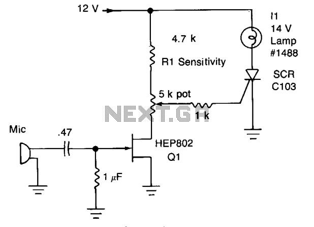
Peaks of signal (adjusted by Rl) greater than approximately 0.7 volts trigger the SCR and illuminate lamp II. The audio from the microphone is amplified by Q1. The circuit described involves a signal detection mechanism that utilizes a silicon-controlled rectifier...

The circuit produces a pleasing and accurate imitation of sound, making it suitable for sound effects such as doorbells. It generates a two-tone effect that closely resembles the sound of a cuckoo. This circuit is designed to create a two-tone...
The tools used in this circuit are designed to create a noisy atmosphere. This circuit is relatively simple and is controlled by two 555 timer integrated circuits (ICs), assisted by other discrete components such as resistors and capacitors. The...

The Door Buzzer circuit utilizes an IC 555 to generate a sound resembling an electric bell. When the switch S1 is pressed, a loud sound is produced. This circuit is designed to be simple and requires minimal components. It...
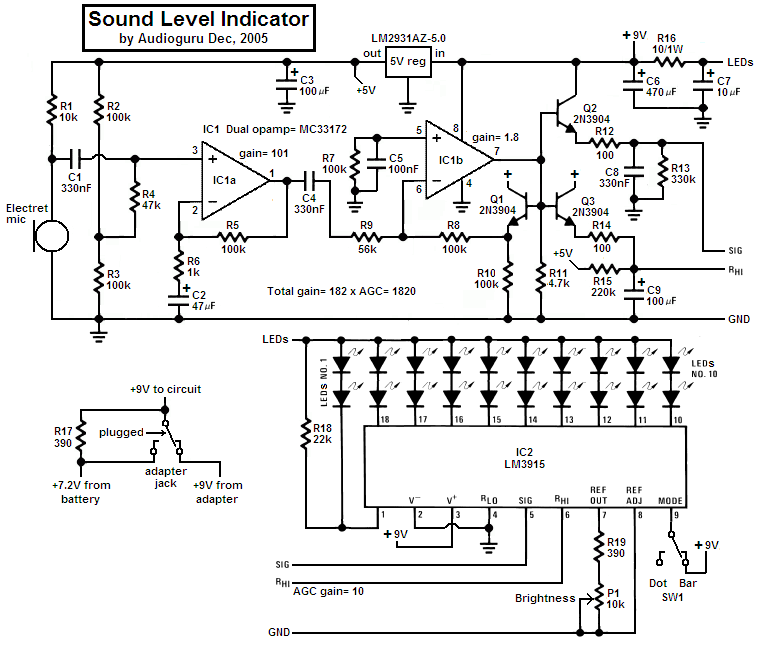
This project utilizes an LM3915 bar-graph integrated circuit (IC) that drives two sets of ten light-emitting diodes (LEDs) across a 30 dB range. The circuit is distinctive as it incorporates an additional 20 dB range through an automatic gain...
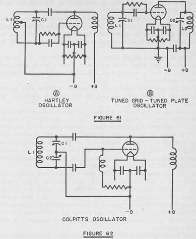
The tuned circuits of capacitance and inductance used in vacuum tube transmitter circuits are often referred to as "tank" circuits, as they serve as reservoirs of RF energy. Blocking capacitors are employed to create a high impedance path for...