
Sound-Level Meter
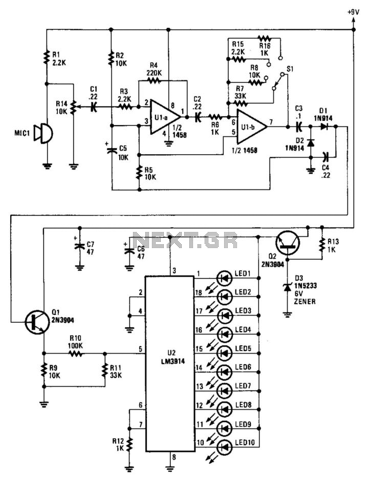
The circuit begins with an electret microphone, which serves as the primary audio input source. Electret microphones are widely used due to their compact size and ability to convert sound waves into electrical signals efficiently. The output from the microphone is routed to an audio amplifier that is designed to enhance the weak audio signal generated by the microphone.
This audio amplifier features switchable gain settings, allowing the user to adjust the amplification level based on the input signal strength or the desired output level. The gain can be controlled through a series of resistors or a potentiometer, enabling flexibility in various applications. The amplified audio signal is then directed to a rectifier circuit, which converts the AC audio signal into a DC voltage. This conversion is essential for driving subsequent components that require a stable DC input.
The rectifier output is connected to an LM3914 bar-graph generator. The LM3914 is a versatile integrated circuit that drives a series of LEDs or a bar graph display, visually representing the amplitude of the input signal. This makes it an excellent choice for audio level indication. The output from the rectifier feeds the LM3914, allowing it to light up the appropriate number of LEDs based on the rectified voltage level.
Additionally, resistor R14 plays a crucial role in providing fine gain control within the amplifier circuit. By adjusting R14, the user can achieve precise control over the amplification, ensuring optimal performance and signal clarity in various environments. This configuration is particularly useful in audio applications where dynamic range and signal integrity are paramount. Overall, this circuit design effectively integrates an electret microphone with an amplifier, rectifier, and visual output display, creating a comprehensive audio processing solution. An electret microphone feeds an audio amplifier/rectifier combination. The amplifier has switchable gain. The rectifier o utput drives an LM3914 bar-graph generator. R14 provides fine gain control. 🔗 External reference
Related Circuits
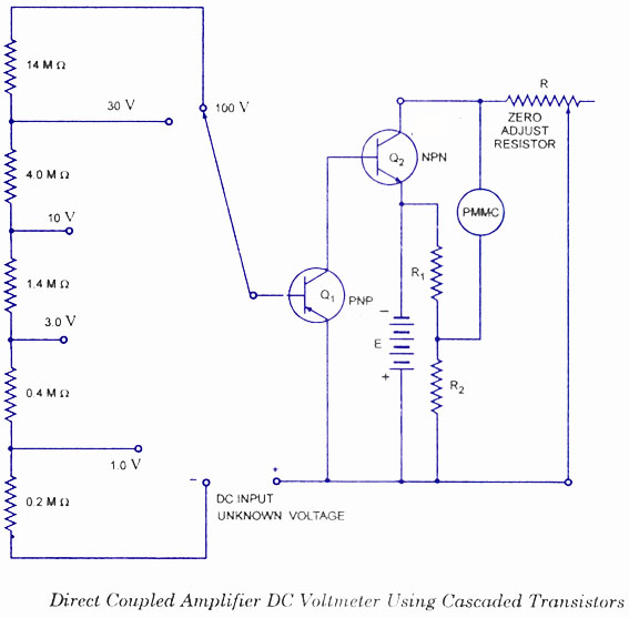
This type of voltmeter is very common due to its low cost. It is designed to measure voltages in the milli-volt range because of limited amplifier gain. The circuit diagram for a direct-coupled amplifier DC voltmeter using cascaded transistors...
This circuit separates an input voltage signal into its components: (1) the absolute value and (2) the polarity or 'sign' (+ or -). It is designed to handle direct current (DC) signals. The circuit operates by utilizing operational amplifiers (op-amps)...
For an introduction to the liquid-level inclinometer and a description of the apparatus and early work on the instrument, refer to Inclinometer Performance. This documentation records day-to-day work on the instrument from February 2008 onwards. Section headings are provided...
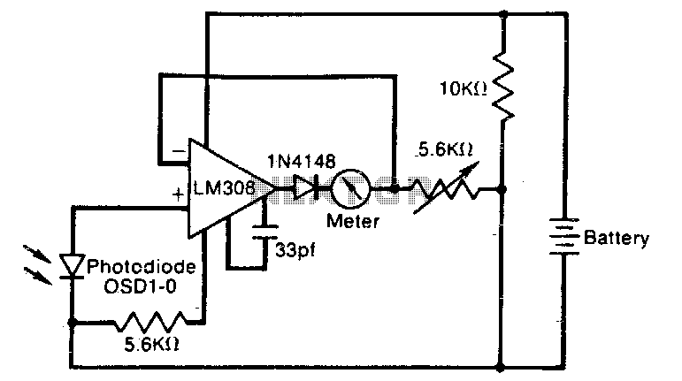
The meter reading is directly proportional to the logarithm of the input light power. The logarithmic circuit behavior arises from the nonlinear diode p-n junction current/voltage relationship. The diode in the amplifier output prevents the output voltage from becoming...
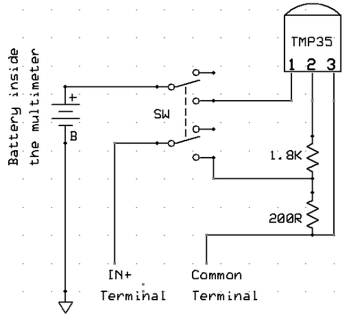
A digital multimeter is a highly versatile instrument that integrates multiple measurement functions within a single unit. Typically, a multimeter encompasses the functionalities of a variable-range ohmmeter, voltmeter, and ammeter, with some models also capable of testing diodes and...
This audio meter can be monitored using a small panel meter with a circuit constructed from discrete components. The audio level meter circuit exhibits a flat frequency response ranging from approximately 20Hz to over 50kHz. The input sensitivity is...