
Sound Level Meter
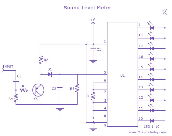
The sound level meter circuit utilizing the LM3915 integrated circuit is designed to provide a visual representation of audio signal levels. The LM3915 is a bar graph or LED dot display driver that can indicate voltage levels corresponding to audio signals, making it suitable for applications in audio equipment and sound measurement.
The circuit typically consists of the LM3915 IC, a power supply, resistors, capacitors, and a display consisting of either LEDs or an LCD. The input audio signal is fed into the circuit through a microphone or audio amplifier output. The IC processes the incoming audio signal and converts it into a proportional voltage level.
The configuration of the LM3915 can be set to operate in either bar graph mode or dot mode, depending on the application requirements. The output pins of the IC are connected to a series of LEDs, which light up in response to the input audio level. This visual feedback allows users to easily monitor sound levels in real-time.
To enhance the functionality of the sound level meter, additional components such as a filter circuit may be included to eliminate noise and ensure accurate readings. The circuit can also be calibrated to adjust the sensitivity of the meter, allowing for precise measurement across different audio environments.
In summary, the sound level meter circuit utilizing the LM3915 is an effective tool for measuring and displaying audio levels, making it valuable in various audio applications, from professional sound systems to home audio equipment.A sound level meter circuit with diagram and schematic using IC LM 3915,which is an audio level measurement chip.Used to display amplifier sound level or a microphone sound level.. 🔗 External reference
Related Circuits
This level measurement circuit utilizes the UAA180 from SIEMENS along with a precision rectification circuit, designated as IC2B. Calibration is achieved in 3 dB steps from one LED to the next, ensuring a high degree of accuracy in measuring...

When the 555 IC goes into timing mode (triggered by an output signal from the sound detector amplifier), the timer's output (pin 3) is set to HIGH for a duration set by C2 and R2. Adjusting R1 will adjust...
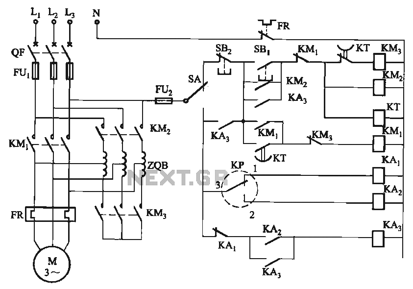
The circuit utilizes a motor auto-voltage transformer for starting. The motor auto-voltage transformer start circuit is designed to provide a controlled method for initiating the operation of an electric motor. This type of circuit is particularly beneficial in applications where...
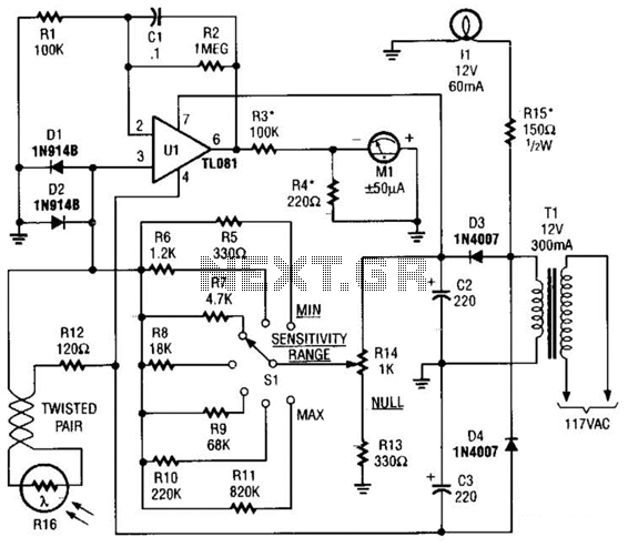
The Meter Ml is a +/-50-uA zero-center D'Arsonval meter movement driven by Ul, a TL081 FET op amp, through R3. The gain of Ul is set to 11 using resistors R1 and R2, while capacitor C1 restricts the bandwidth...
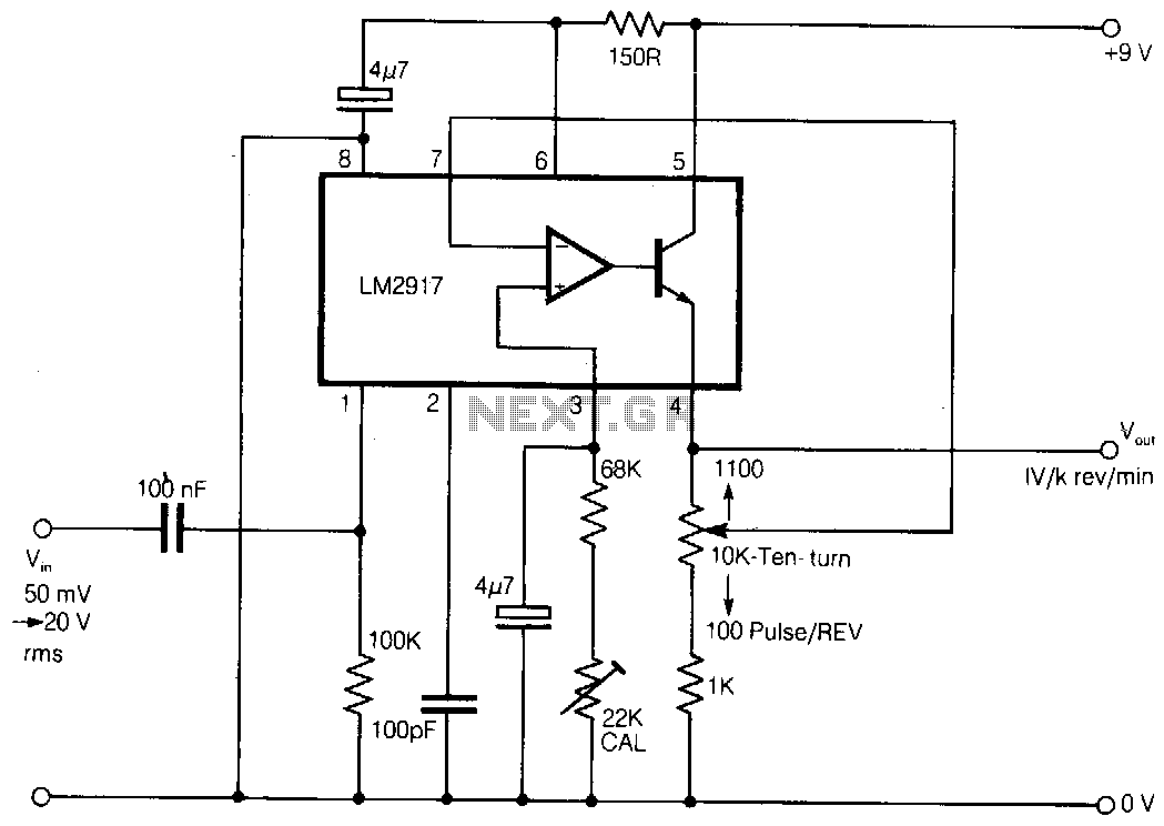
Here is a simple tachometer circuit for use with a hand-held DVM or portable chart recorder. A novel feature is that the source frequency pulse/rev rate can be directly set on a ten-turn potentiometer to provide a convenient calibration...
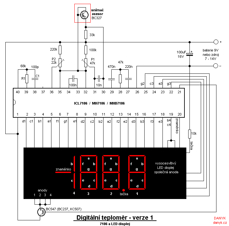
Two versions of a homemade digital thermometer utilizing the ICL7106 are presented. One version features an LED display, while the other employs an LCD display. Both variants utilize a silicon transistor as a temperature sensor, with temperature determined by...
Warning: include(partials/cookie-banner.php): Failed to open stream: Permission denied in /var/www/html/nextgr/view-circuit.php on line 713
Warning: include(): Failed opening 'partials/cookie-banner.php' for inclusion (include_path='.:/usr/share/php') in /var/www/html/nextgr/view-circuit.php on line 713