
Camper Meter
The water level estimation device utilizes a combination of sensors and microcontroller technology to provide accurate readings of the water level in a tank. Typically, this device may incorporate ultrasonic sensors, capacitive sensors, or float switches, depending on the desired accuracy and application requirements.
In an ultrasonic sensor setup, the device emits sound waves that bounce off the surface of the water. The time taken for the sound waves to return to the sensor is measured, and this data is used to calculate the distance to the water surface. This distance can then be translated into a water level reading, which is displayed on an LCD screen or transmitted to a mobile application via Bluetooth or Wi-Fi.
Alternatively, capacitive sensors can be used to detect the water level by measuring changes in capacitance caused by the proximity of water. This method is often more reliable in environments where turbulence or debris may affect ultrasonic measurements.
For a float switch mechanism, a buoyant switch is positioned within the tank. As the water level rises or falls, the float moves accordingly, opening or closing a circuit that can activate an LED indicator or send a signal to a microcontroller, which can then relay the information to the user.
Power supply considerations for this device may include battery operation or connection to the caravan's electrical system. Low-power components are preferred to extend battery life, and the device may feature a sleep mode to conserve energy when not in active use.
The schematic for this water level estimation device would include the chosen sensor type, a microcontroller (such as an Arduino or Raspberry Pi), a power supply circuit, and output interfaces for user notifications. Proper calibration and installation are critical to ensure accurate readings, particularly in varying environmental conditions experienced in camping scenarios.This is a gadget that will estimate the amount of water left in the water tank of a caravan or camping unit.. 🔗 External reference
Related Circuits
A schematic diagram for a broadband QRP SWR metering circuit intended for use in a QRP antenna tuner. The circuit allows the user to press a momentary DPDT switch to observe an LED indicator while adjusting the capacitors of...
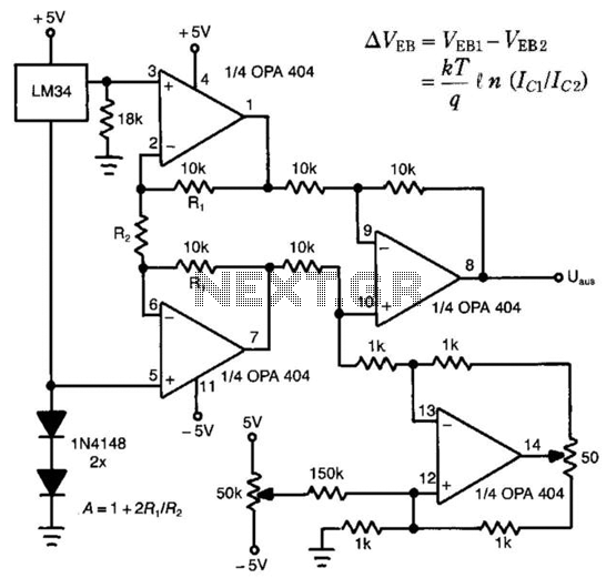
The LM34 is utilized as a sensor in the design of this linear thermometer. Its output represents the difference between two base-emitter voltages (Veb) of two transistors that operate at different collector-current densities. These current densities are denoted as...
This application note outlines the design of a PC-based, 14-bit data acquisition system. It adopts a systematic approach, incorporating all essential components: analog, digital, hardware, and software. The document elaborates on each phase, emphasizing the testing of individual systems...
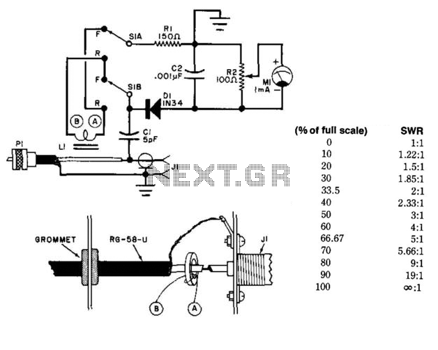
This circuit utilizes a toroidal pickup coil encircling the center conductor of a coaxial cable to measure the SWR (Standing Wave Ratio) of an antenna. The inductor (LI) consists of two turns of #26 enameled wire wound on a...
This digital thermometer indicates the temperature measured with an NTC using 7 LEDs. The circuit works using an opamp, the well-known 741, which amplifies the voltage difference between its plus and minus input. This amplification (sensitivity) can be set...
A well-tuned antenna system functions like a dummy load, meaning the Standing Wave Ratio (SWR) is 1.2:1 or lower; however, the effective radiation range is limited. The issue at hand is insufficient radiation. To diagnose this, one can measure...