
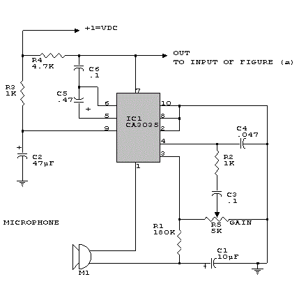
sound sensor schematics
The sound sensor schematic operates by detecting sound levels in the environment and activating a relay based on the intensity of the sound. The core component, an integrated circuit, serves as the sound detection unit. It converts acoustic signals into electrical signals, which are then processed to determine if the sound exceeds a predefined threshold.
The two transistors in the circuit function as amplifiers and switches. When the input from the IC indicates that the sound level is sufficient, the first transistor is triggered. This, in turn, activates the second transistor, which controls the relay. The relay can be used to switch on or off various devices, such as alarms or lights, depending on the application.
The inclusion of a variable resistor (VR) in the design allows for fine-tuning of the sensitivity of the sound detection. By adjusting the VR, the threshold for sound detection can be modified, enabling the user to set the circuit to respond to softer or louder sounds as needed.
This schematic is advantageous for various applications, including security systems, sound-activated lighting, and other automation tasks. Its simplicity and effectiveness make it accessible for individuals with basic electronic skills, promoting ease of construction and implementation.Here is simple sound sensor schematic, it`s use only one IC and and two transistor to drive the relay. this schematics can change the sensitivity using VR resistor also. I think this schematics is very usefull and can build anyone. 🔗 External reference
Related Circuits
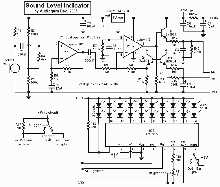
This project uses an LM3915 bar-graph IC driving two sets of ten LEDs for a 30dB range. The circuit is unique because it has an additional range of 20dB provided by an automatic gain control to allow it to...
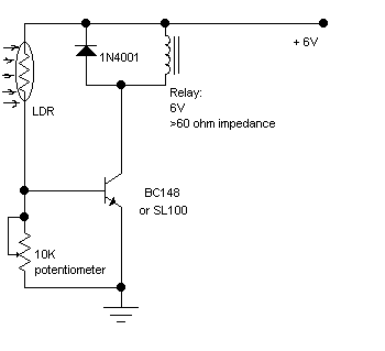
The following circuit illustrates a Light Barrier Sensor Detector Circuit Diagram. Features include a single transistor, an adjustable potentiometer, and a 6V power supply. The Light Barrier Sensor Detector Circuit is designed to detect the presence of an object by...
A piezoelectric sounder (self-drive type) consists solely of a piezoelectric diaphragm with a feedback electrode and is utilized in conjunction with an external drive circuit. The drive circuit for both types of sounders is a simple configuration comprising one...
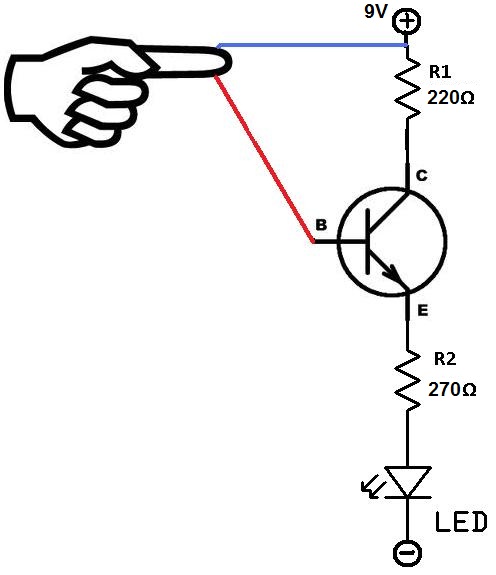
This project utilizes two wires, one red and one blue, which function as touch sensor wires. When a person touches both wires, the circuit closes, allowing current to flow and illuminate the LED. A 9-volt battery or an external...
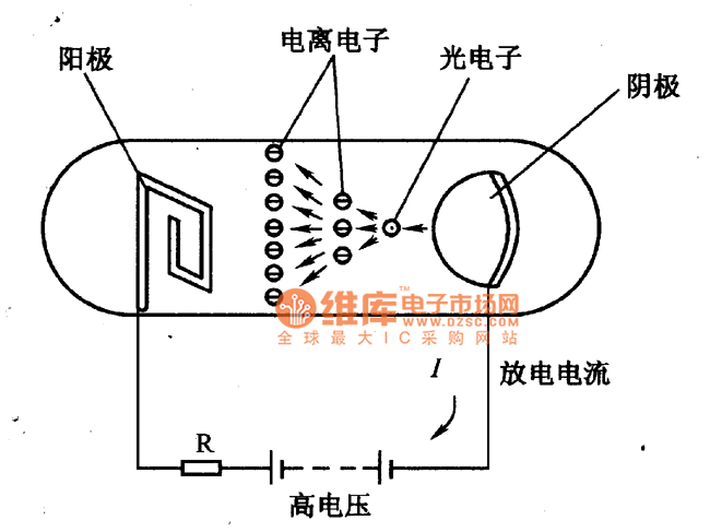
The figure illustrates a schematic circuit of a UV sensor. When voltage is applied between the cathode and anode, and UV radiation passes through the quartz glass tube on the cathode's optical surface, the cathode material, which is coated...
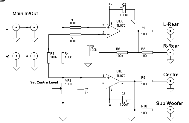
Simple Surround Sound Decoder. Introduction This surround-sound decoder is based on the Hafler principle, first discovered by David Hafler sometime in the early 1970s. The original idea. The simple surround sound decoder utilizes the Hafler principle to create an immersive...