
SP10 motor controller

The PC-board layout represents a critical aspect of electronic design, as it dictates the arrangement of components and the routing of electrical connections. The adjustments made to the design may involve alterations in the placement of components, changes to the trace widths, or modifications to the grounding scheme.
In a typical PCB design, careful consideration is given to the signal integrity, thermal management, and electromagnetic interference (EMI) mitigation. The layout should ensure that high-frequency signals are routed with minimal inductance and capacitance, which may require the use of controlled impedance traces. Additionally, components that dissipate significant heat should be positioned to allow for effective thermal dissipation, potentially incorporating heat sinks or thermal vias.
Grounding is another crucial factor; a solid ground plane can help reduce noise and improve overall circuit performance. The choice of materials, such as the substrate type and copper thickness, also plays a vital role in the final performance of the PCB.
The modifications mentioned may reflect an iterative design process, where feedback from testing or simulation leads to enhancements in the layout. These changes can be aimed at improving manufacturability, reducing costs, or enhancing reliability under varying operating conditions.
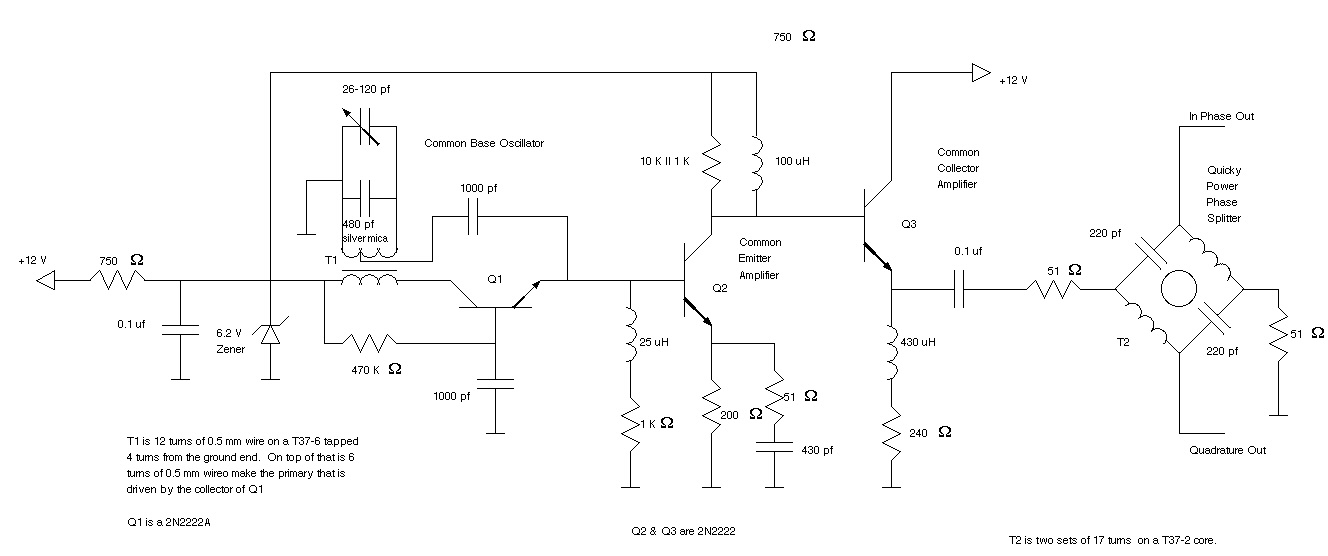
In conclusion, the refined PCB layout is an essential step towards achieving optimal performance and functionality in electronic circuits, and each modification contributes to the overall effectiveness of the design.Those who`ve scrutinised my PC-board layout very closely, will see that I`ve changed the design slightly from the circuit which I posted a while back. .. 🔗 External reference
Related Circuits
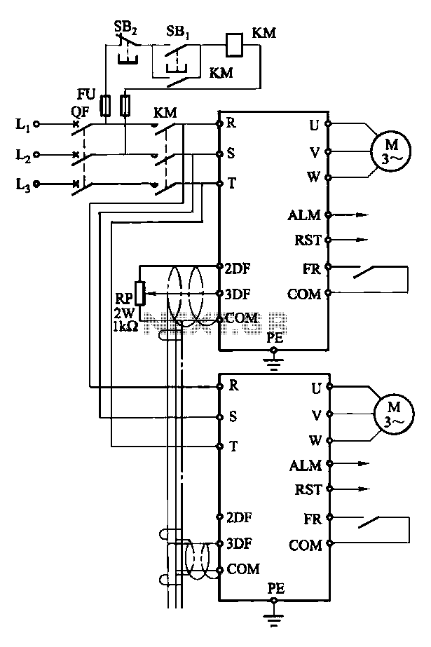
Each motor operates with an independent drive; however, only one frequency is utilized for a specific device. This setup employs a single RP potentiometer to control multiple motors in parallel. In this configuration, the circuit design allows for multiple motors to...
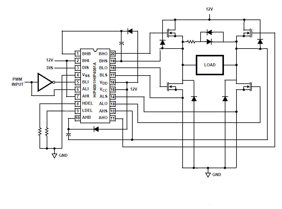
An individual is experiencing an unusual issue while utilizing an Intersil HIP4081A H-bridge driver integrated circuit (IC). The IC is connected to an Arduino microcontroller unit (MCU). The Intersil HIP4081A is a high-performance H-bridge driver designed for driving DC motors...
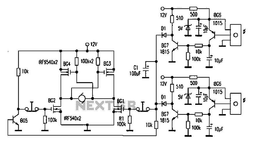
Automatic door control systems typically have a high market price for finished products. The proposed method is suitable for home use, utilizing easily accessible components. This design is ideal for those interested in creating their own automatic door system....

Diodes can be utilized instead of pull-up resistors, while isolating the DC load from the trigger circuit through junction drops and a 10nF capacitor. Excessive power from the solar cell may cause the motor to operate too frequently or...
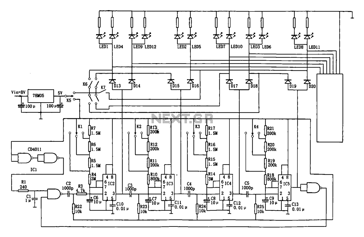
This document describes an automatic traffic intersection light control circuit. It features four monostable delay circuits, which consist of four 555 timer integrated circuits (IC2 to IC5) and several RC components interconnected. An 8V input voltage is regulated through...
Ralph Stirling, KC3F, and another engineer developed the first generation of a digital signal processing (DSP) system using the Texas Instruments C5X DSK starter kit. The second generation represents a significant advancement, utilizing the more appropriate Motorola DSP56002EVM evaluation...