
Space Horticulture Circuit
The proposed circuit operates effectively within the specified parameters, utilizing a 555 timer IC configured in astable mode to generate a square wave signal at 3Hz frequency with a 50% duty cycle. The duty cycle indicates that the LED will be on for half of each cycle, ensuring a balanced illumination effect during operation. The choice of a 1µF capacitor is critical in determining the timing intervals, as it directly influences the charge and discharge rates within the 555 timer circuit.
The TIP120 transistors serve as the primary switching elements in this design. The first TIP120 (T1) is responsible for modulating the power delivered to the strobe LED lighting module, effectively turning it on and off in response to the output from the 555 timer. The second TIP120 (T2) acts as a compensatory element, addressing the voltage drop experienced by T1. By maintaining the voltage drop across T1, T2 ensures that the control LED modules receive a consistent voltage level, thereby achieving uniform brightness across all LEDs.
In this configuration, resistor R4 plays a vital role by providing a forward bias to T2, keeping it continuously in the 'on' state when power is supplied. This arrangement ensures that the control LED modules operate effectively without experiencing fluctuations in brightness caused by variations in the voltage drop across T1.
The power supply for the entire circuit is a 12 VDC wall transformer, which is a common and practical solution for such applications. The integration of an AC appliance timer allows for automation of the lighting system, enabling it to operate for a predetermined duration (12 hours in this case), which is particularly useful for applications requiring periodic illumination.
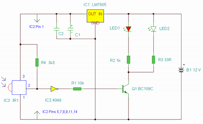
Overall, the design effectively combines timing, switching, and power management to achieve the desired strobe effect while ensuring consistent performance across the LED modules. The schematic representation of the circuit, including the arrangement of components and connections, is essential for visualizing the operational flow and verifying the integrity of the design.The optimum duty cycle and frequency for the strobe photoperiod needs to be determined. In other words we`re flying blind in regard to optimum frequency and duty cycle. The circuit I designed is 3Hz with a 50% duty cycle. I chose this frequency based upon using a convenient 1-uF capacitor, for a 555 timer IC. The schematic is shown in figure 2 (be low). The output from the 555 timer (pin 3) is connected to the base of NPN Darlington Transistor (TIP120) T1. The NPN transistor switches the current on and off to the strobe LED lighting module. There is a voltage drop across the collector-emmiter of the TIP 120 transistor. To insure the equal brightness from both the LED modules, I place a dummy TIP120 transistor, T2, in line with the control LED module (see figure 3, below).
The transistor T2 matches the voltage drop across T1 to help supply an equal voltage to the control LED modules. The T2 transistor is kept forward bias (always on), when power is applied through resistor R4 (2. 2K ohm). The voltage drop I measured across the TIP120 transistors is approximately 1. 5 volts. An overall view is shown in figure 4 (above). A 12 VDC wall transformer powers the circuit. The wall transformer is plugged into an inexpensive Radio-Shack AC appliance timer set for a 12 hour on period.
The wall transformer supplies voltage to both circuits. 🔗 External reference
Related Circuits
This project has been specially designed to introduce you to SMD (Surface Mount Devices). Surface Mount is really not new. It started as far back as 1940 with a hybrid circuit in a digital watch. A chip was cemented...
Dark Activated Switch or Porch Light Switch. This circuit activates a relay when the light level drops below a preset threshold. The light sensitivity can be adjusted using variable resistor VR1, and the relay contacts can control an external...
This is an enhanced infrared (IR) remote control extender circuit. It features high noise immunity, resistance to ambient and reflected light, and an increased operational range. The improved IR remote control extender circuit is designed to extend the range of...
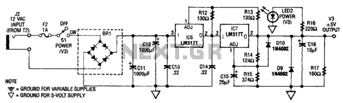
The power supply presented is intended to function with a wall transformer. This circuit can be utilized alongside a variable supply for testing circuits in a laboratory setting. T2 serves as a 12-V wall transformer. The power supply circuit is...

FIG M is a variable speed motor control for the opening and closing of a wicket gate. It features an electric governor. The system is activated by a power switch (SA) located on the front grid, and a toggle...
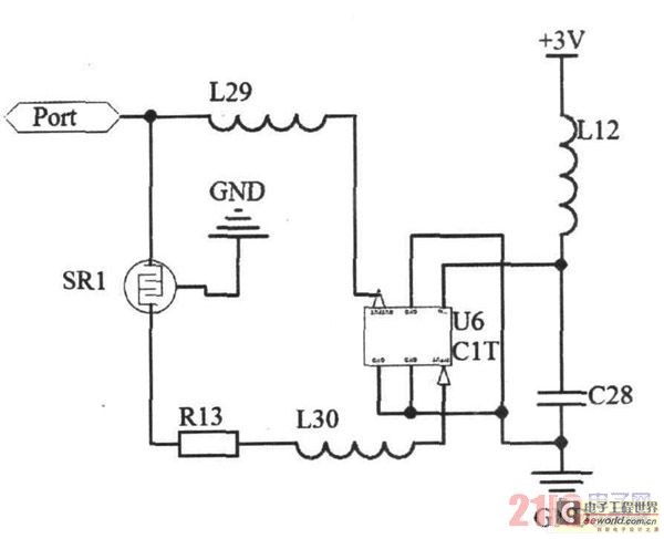
Due to the small size, high precision, and sensitivity of surface acoustic wave (SAW) sensors, along with their cost-effectiveness, a SAW gas sensor has been developed. This sensor comprises a surface acoustic wave device, a sensitive membrane, and the...