
Speaker Microphone circuit diagrams
The circuit utilizes a loudspeaker as a microphone by converting acoustic energy from sound waves into electrical signals. The speaker cone's movement, caused by sound waves, induces a change in the voice coil's position within the magnetic field, generating a small voltage. This voltage is then amplified through a two-stage transistor amplifier configuration.
In the first stage, a transistor is configured in common base mode, which is particularly beneficial for low-impedance sources like the loudspeaker. The common base configuration provides a high voltage gain while minimizing the input impedance, allowing for effective signal transfer from the speaker. The choice of this configuration is crucial for enhancing the circuit's performance, especially in capturing and amplifying the weak signals produced by the speaker.
The second stage employs an emitter follower configuration, which is directly coupled to the first stage. This stage is designed to maintain a low output impedance, enabling the circuit to drive longer cables without significant signal degradation. Although the voltage gain in this stage is slightly less than one, the benefits of low output impedance and high current drive capability make it suitable for various applications.
The circuit is versatile, accommodating speaker cones with diameters between 1 inch to 3 inches and speaker impedances ranging from 4 ohms to 64 ohms. The inclusion of an adjustable 8.2-ohm resistor allows for impedance matching, optimizing performance based on the specific characteristics of the loudspeaker used.
Overall, while the audio quality produced by this circuit may not reach the clarity of traditional microphones, it offers an innovative and cost-effective solution for applications where high fidelity is not the primary concern.This circuits allows you to use a cheap loudspeaker as a microphone. Sound waves reaching the speaker cone cause fluctuations in the voice coil. The voice coil moving in the speakers magnetic field will produce a small electrical signal. The circuit is designed to be used with an operating voltage between 6 and 12 volts dc. The first transistor op erates in common base mode. This has the advantage of matching the low input impedance of the speaker to the common base stage, and secondly has a high voltage gain. The second stage is direct coupled and operates in emitter follower. Voltage gain is slightly less than unity, but output impedance is low, and will drive long cables. Speech quality is not as good compared to an ordinary or ECM microphone, but quite acceptable results can be obtained.
Speaker cones with diameters of 1 inch to 3 inches may be used. Speaker impedance may be 4 ohm to 64 ohm. The 8. 2 ohm resistor value may be changed to match the actual speakers own impedance. 🔗 External reference
Related Circuits
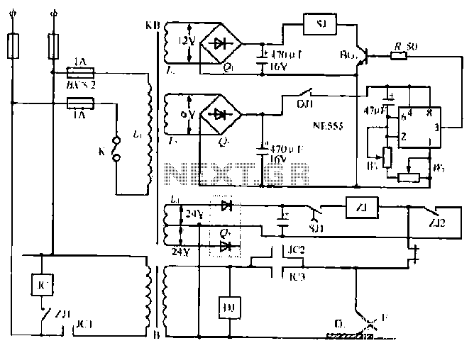
The NE555 timer circuit functions as a vibration generator. The input pin 3 produces pulse frequencies ranging from 5 to 20 Hz. The circuit includes a fan that operates within a bamboo enclosure. The barrel section is designed to...
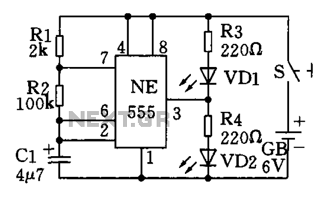
The circuit utilizes a 555 timer as the central component of a flashing light circuit. In normal operation, the light-emitting diodes (LEDs) VD1 and VD2 alternate flashing. The circuit comprises the NE555 timer, resistors R1 and R2, and capacitor...
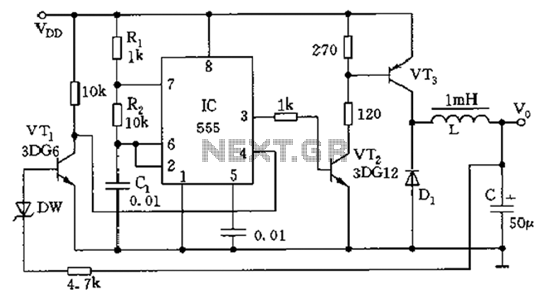
The circuit consists of a 555 timer configured as an astable multivibrator along with resistors R1 and R2 and capacitor C1. It generates an oscillation frequency of approximately 10 kHz with a duty cycle close to 50%. Transistors VT2...
The Arduino Uno features an ATMEGA328P-PU microcontroller and various additional components on the board. The objective is to program the microcontroller without relying on the Arduino software, utilizing only the essential components. The goal is to develop projects independently...
The purpose of this circuit is to animate shop windows using a capacitive sensor positioned behind a postcard-like banner. The card is placed against the glass inside the shop window, allowing visitors to activate the relay by placing their...
A frequency synthesizer circuit diagram has been found, but clarification is needed regarding a component connected to VDD from pin 9, VSS from pin 8, and pin 12, which is linked to the phase comparator 2. The component in...