
Car Door Keypad Using LIN
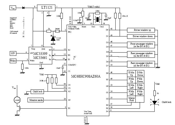
The functionality of a car door can be compared to that of a multi-key input device, where simultaneous activation of multiple components is necessary to achieve a desired outcome. In automotive design, this concept is particularly relevant in the context of door locking mechanisms and electronic control systems.
In a typical car door, there are various inputs that can be engaged at once, such as the door handle, lock button, and window controls. These inputs are often integrated into a centralized control unit that manages the operation of the door's mechanisms. For example, pressing the door handle while simultaneously pressing the unlock button can allow for quick access to the vehicle, illustrating the need for multi-key functionality.
The electronic schematic for a car door system may include components such as microcontrollers, relays, and sensors. The microcontroller serves as the brain of the system, processing inputs from various switches and sensors. Relays are used to control the locking mechanism and window motors, allowing for high-current operations that are necessary for these functions. Additionally, sensors may be incorporated to detect the position of the door and ensure that it is securely locked or unlocked.
In summary, the design of a car door system emphasizes the importance of multi-key input functionality, which is essential for user convenience and safety. The integration of electronic components allows for sophisticated control and enhances the overall user experience.A car door differs from a calculator or a phone in that it makes sense to press more than one key at a time 🔗 External reference
Related Circuits

This version of the Link is intended for users who require an affordable and reliable intercom system without access to an external telephone line. It is suitable for environments such as preschools, hobby farms, or small workshops and factories,...
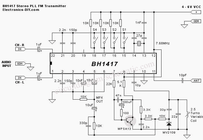
This circuit diagram is part of an RF circuit. It features an FM transmitter circuit diagram using the BH1417 integrated circuit from RHOM, which incorporates multiple functionalities in a compact design. The IC includes pre-emphasis and a limiter to...
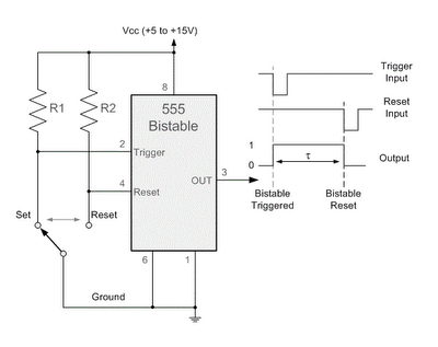
By applying a "LOW" signal to the Trigger input (pin 2) while the switch is in the Set position, the output state changes to "HIGH". Conversely, applying a "LOW" signal to the Reset input (pin 4) while the switch...
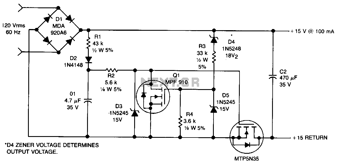
This non-isolated, unregulated converter with minimal components serves as a bridge between low-power zener regulation and the higher power applications of a 60-Hz input transformer. It is designed for scenarios where a non-isolated power supply can be utilized safely....
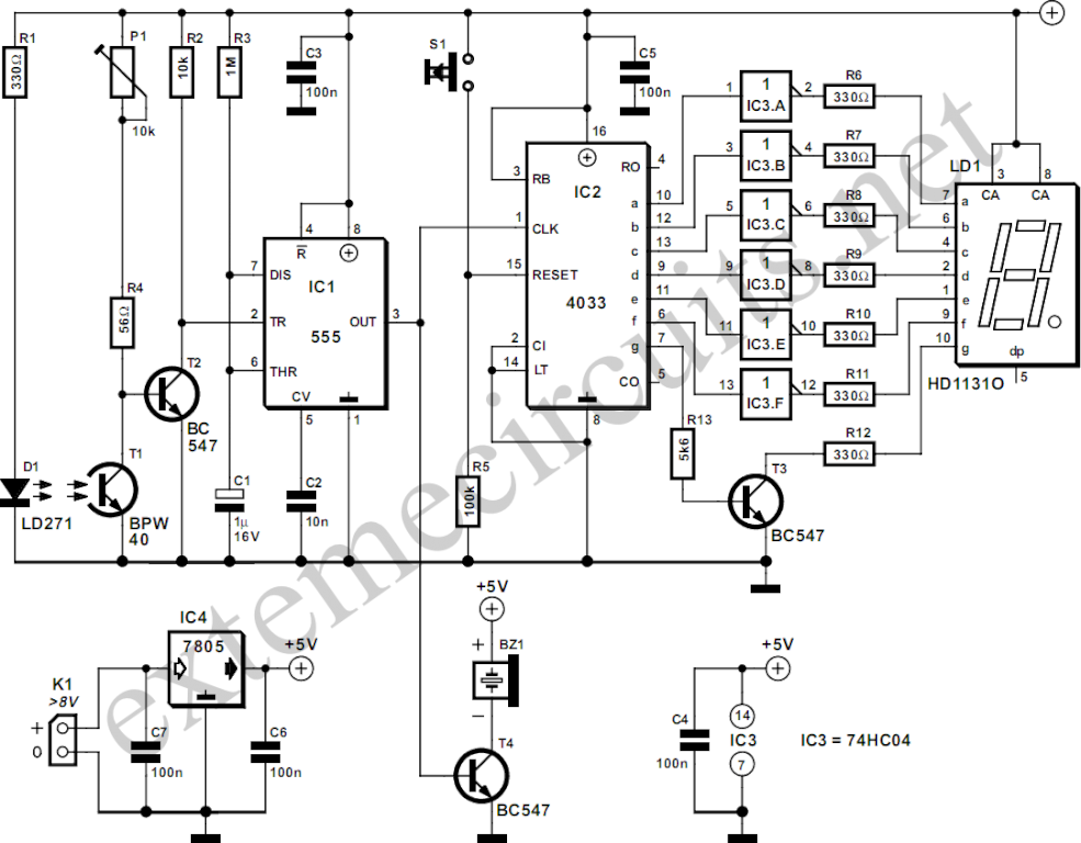
The circuit described here counts the number of times an infrared beam is interrupted. It can be utilized to count the number of individuals entering a room or to track how often an object, such as a ball, passes...
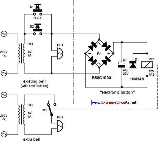
In certain situations, it may be necessary to adopt a more complex approach, even when simpler alternatives exist. This applies in the current scenario, where the objective is to install a second doorbell. To implement the addition of a second...