
Speech Board for SPO256
Design goals include a compact board size (hence the nested chips), minimal control lines (four), various construction options, and a high-quality circuit board. The layout was designed using ExpressPCB software. The board is double-sided, drilled, and solder reflowed, featuring four mounting holes at the corners, a solder mask, and silk-screening. The dimensions are approximately 1.5 inches by 2.5 inches (about 3.8 cm by 6.4 cm), with a densely packed design that places the shift register beneath the socket for the SPO-256. The bits are clocked out from the least significant bit (LSB) to the most significant bit (MSB). This board requires a moderate level of soldering proficiency and a fine soldering iron. It employs a shift register to convert serial input (not RS232 serial) to parallel for the SPO256, requiring only four control lines: C - CLK for the shift register (pin 0 in the circuit), I - INA for the shift register (pin 1), A - ALD allophone load for the SPO256 (pin 2), and L - LRQ for the SPO256 (pin 3).This board does NOT use the CTS256AL2 text-to-speech chip. [It would seem that both SpeechChips.com and JDR still have some of these chips, though, if you're looking for some.] However, you could easily use this board to hold the SPO chip and amplifier and connect it to your own CTS circuit. All necessary pin connections do have an available solder pad for off-board connections. Additionally, there is a socket for a 12C508/9 PIC which can reduce control pin count down to 2, or even to 1.
This would also allow the line-twiddling to be offloaded from the Stamp or whatever else is the master controller. I've done the bulk of the code with some debugging and fine-tuning left. Both the PIC and audio amp [LM386] are optional and there is a provision for adding either an LED on-indicator OR a separate power supply for the amp.
Amp gain is 200 and seems to be adequate with 5v supply. There is some room for a trimmer cap for the crystal in case your SPO256 chip is overly sensitive to the clock stability [as one of mine is]. The board can also be fitted with a 5v voltage regulator if you can't provide it with a regulated supply.
But this option is not recommended. Design goals: Small board size [hence the nested chips] Few control lines [4] Some construction options High quality circuit board Layed out with ExpressPCB s/w. [Visit Express PCB site (Manufacturing Specifications for Production Service) for more information about their product.] Double-sided, drilled, solder reflowed 4 mounting holes on corners solder mask silk screen.
Pretty small [1.5" x 2.5" (ca. 3.8 cm x 6.4 cm)] and fairly densely packed the shift register is UNDER the socket for the SPO-256 bits are clocked out from LSB to MSB This board equires a moderate level of soldering proficiency and a fine soldering iron. Uses shift register to convert serial input [NOT RS232 serial] to parallel for SPO256. Only requires 4 lines to control: C - CLK for shift register [pin 0 in circuit below] I - INA for shift register [pin 1] A - ALD allophone load for SPO256 [pin 2] L - LRQ for SPO256 [pin 3]
🔗 External reference
Related Circuits
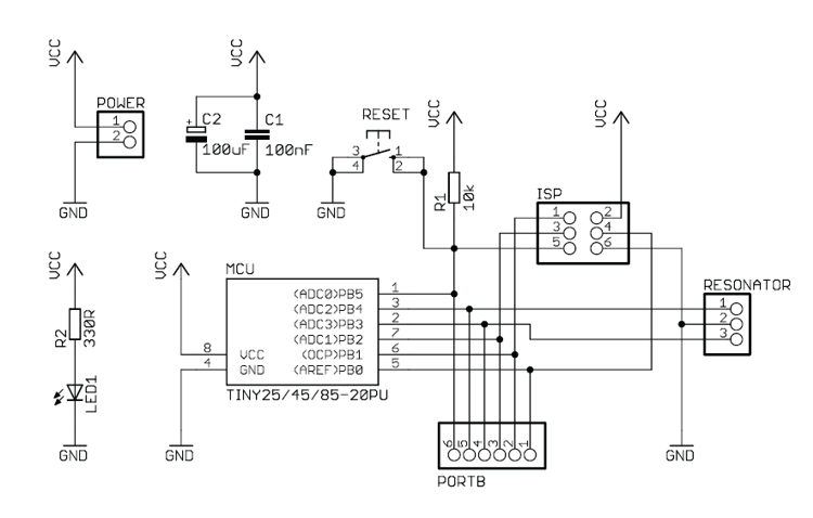
This handy breadboard header for ATTiny 25/45/85 microcontroller is a new design based on the original idea from Tinkerlog. Maybe the most useful feature is that it can provide power to the vertical breadboard strips while connecting all six...
This project is basically what I use for a quick prototype, or for just mucking about with an idea. It is easy to make, and only needs a medium size sheet of un-etched printed circuit board (or possibly two)....
8051SBC USB and GLCD Expansion Board, electronic circuit schematic wiring diagram for the 8051SBC USB and GLCD Expansion Board. The 8051SBC USB and GLCD Expansion Board is designed to enhance the functionality of the 8051 microcontroller system by providing additional...
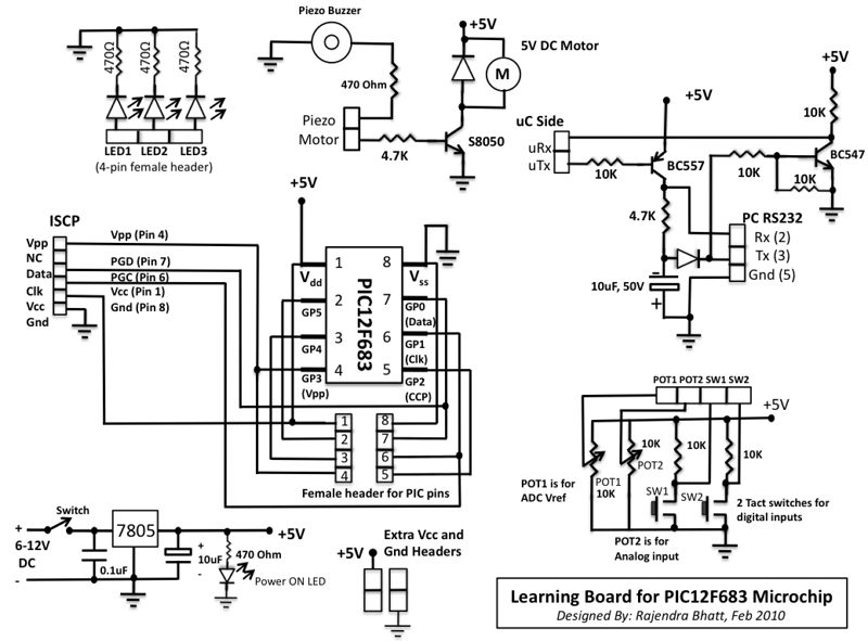
This microcontroller fascinated me a lot because I wanted to see what we can do with an 8-pin microcontroller (out of which 2 pins goes to power supply, so actually just 6-pins are left for I/O). So I thought...
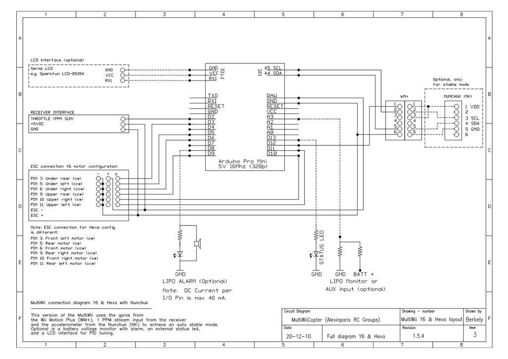
This is a video showcasing a test flight of the Quad Rotor Observer (QRO) v8, which is equipped with the FCWii board, Wii Motion Plus gyroscopes, and Nunchuk accelerometers. The Quad Rotor Observer (QRO) v8 is an advanced quadcopter designed...

The demonstration circuit operates in the HM2007's manual mode. This mode uses a simple keypad and digital display to communicate with and program the HM2007 chip. When the circuit is turned on, the HM2007 checks the static RAM. If...
Warning: include(partials/cookie-banner.php): Failed to open stream: Permission denied in /var/www/html/nextgr/view-circuit.php on line 713
Warning: include(): Failed opening 'partials/cookie-banner.php' for inclusion (include_path='.:/usr/share/php') in /var/www/html/nextgr/view-circuit.php on line 713