
Motorcycle anti-theft lock electronic circuit
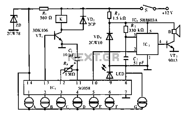
The 5C058 ASIC lock circuit is designed for secure access control applications. It utilizes a sequence of valid key inputs to unlock, ensuring that only authorized users can gain access. The valid key inputs are connected to pins 1 through 6, which are linked to a key switch mechanism. When the correct sequence of keys A through F is pressed, the circuit recognizes the input and activates the unlocking mechanism.
The negative power supply is connected to pin 7, which ensures that the circuit has a common ground reference, essential for stable operation. The false key input terminal at pin 8 is a critical feature that enhances the security of the lock. This terminal can be connected to an invalid key switch, allowing the circuit to identify and disregard spurious inputs that do not conform to the valid key sequence.
The circuit's ability to accept mixed inputs is a unique feature that provides flexibility in operation. Users can press multiple keys simultaneously or in quick succession without triggering a false unlock response. This design consideration is important in environments where security is paramount, as it prevents unauthorized access through accidental or unintentional key presses.
Overall, the 5C058 ASIC lock circuit represents a robust solution for electronic locking mechanisms, combining ease of use with advanced security features to protect sensitive areas or devices.Circuit works: lC1 is lock ASIC 5C058. Its 1-6 feet were even outside the key switch to the positive power supply, which is six valid key input, open lock A-F must comply with this order. 7 feet for the negative power. 8 feet false key input terminal, even outside an invalid key switch. You can take one or several mixed into the keyboard in order to leave spurious.
Related Circuits
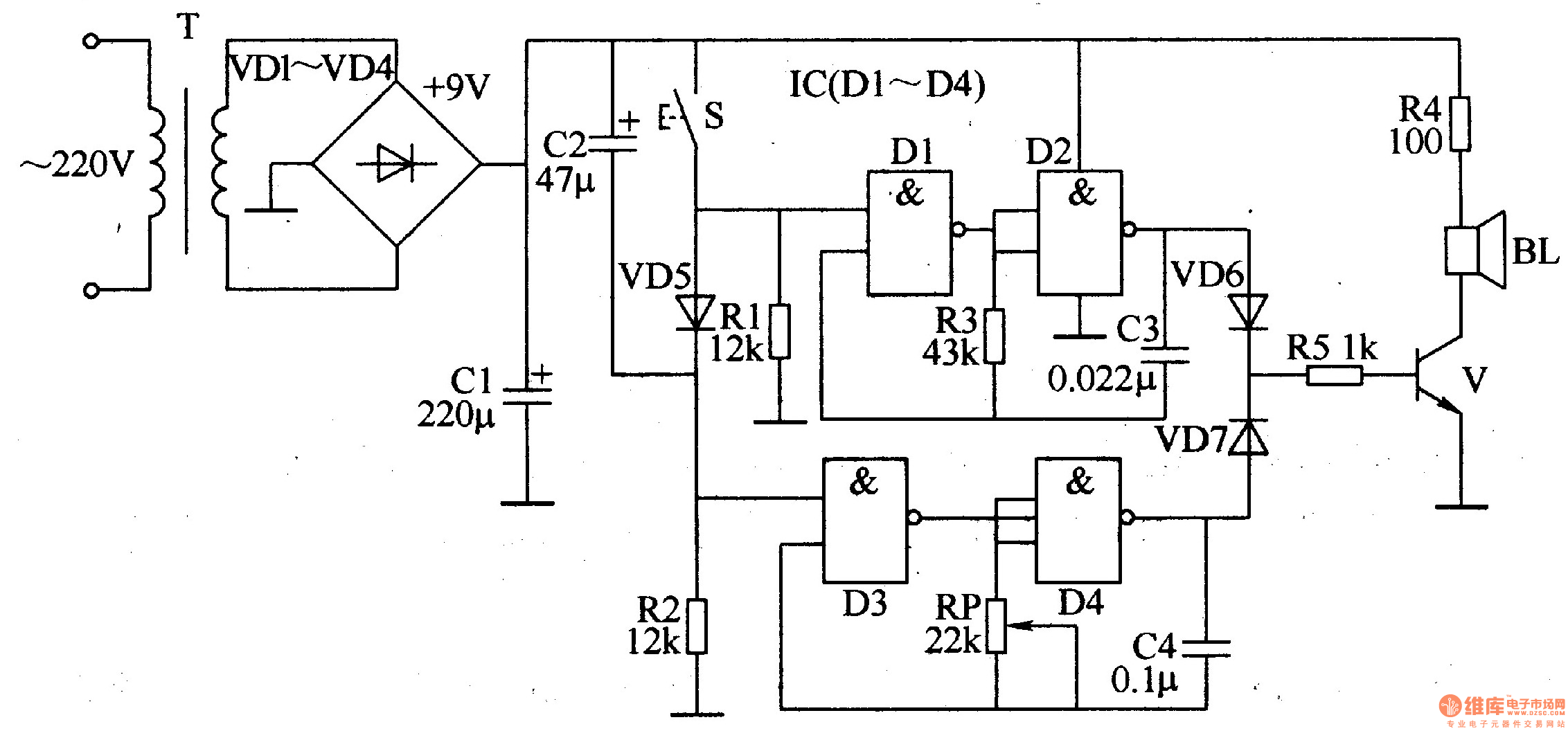
The ding-dong electronic doorbell circuit consists of a power supply circuit, a trigger control circuit, and an audio oscillator output circuit. The power supply circuit includes a power transformer (T), rectifier diodes (VD1-VD4), and a filter capacitor (C1). The...
A thermistor positioned as indicated creates a heat-activated sensor. Variations in temperature will modify the output of the operational amplifier, triggering the relay and illuminating the LED. Reversing the placement of the thermistor and the 47k resistor converts the...
To enhance usability during nighttime, the receiver features a scale with bias lighting, and the surface behind the scale is coated with a fluorescent material. To activate the scale illumination, press button 3. Radio programs can be listened to...
Build a CD47 Nixie Clock. Power: approximately 100 Watts. Some may question if this is over-engineered, but it will be justified by the project's outcome. The Nixie tubes will be turned off when not in use to prolong their...
To obtain the power supply graphs on the previous page, the circuit is designed to independently monitor the power sources with the addition of a few resistors. Diode D3 allows the solar panel voltage to charge the batteries, while...

This circuit utilizes the Mitsubishi M65830 Digital Delay chip, which has proven to be simple and effective for applications requiring a fixed delay. The serial data necessary for achieving various delay settings is not readily available and would significantly...
Warning: include(partials/cookie-banner.php): Failed to open stream: Permission denied in /var/www/html/nextgr/view-circuit.php on line 713
Warning: include(): Failed opening 'partials/cookie-banner.php' for inclusion (include_path='.:/usr/share/php') in /var/www/html/nextgr/view-circuit.php on line 713