
Speed Reaction Test Circuit
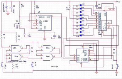
The speed test circuit is designed to assess human reaction time through a user-friendly interface. The core components include the 555 timer IC, which generates a precise timing sequence, and the 7490 decade counter, which counts the pulses output by the timer. The 7445 decoder translates the counter's binary output into a format suitable for driving the LEDs, allowing for a visual representation of the counting process.
When the circuit is powered on and the start button is pressed, the 555 timer is activated, producing a rapid succession of pulses. These pulses increment the count in the 7490 counter, which, in turn, activates the LEDs in a sequential manner. The illumination of the LEDs provides immediate feedback to the player, indicating the countdown to the reaction test.
Upon pressing the stop button, the last LED lit will remain illuminated, signaling the end of the test. The timing of the last LED provides a visual cue for the player to gauge their reaction time. The circuit's design ensures that the player can easily reset the game and begin a new round by pressing the reset button, which clears the counter and prepares the circuit for the next test.
The circuit's power requirements are modest, operating at 5V with a current draw of 120mA, making it suitable for battery operation or low-power applications. The adjustable frequency via potentiometer P1 allows for customization of the reaction test's difficulty, accommodating different skill levels.
Incorporating an additional LED with a 200-ohm resistor as an indicator enhances the user experience by providing a clear visual signal that the system is ready for the next round. This feature ensures that players are aware of the circuit's status without needing to monitor other components actively. Overall, this speed test circuit is an effective and engaging tool for measuring reaction times, suitable for various applications in both recreational and educational settings.Speed test circuit reaction of is simple planning. This circuit functions for game to test speed reaction of a man. Mode of the action of this peripheral is hardly easy to be comprehended. This thing is caused by this peripheral only lapped over by some Logical Integrated Circuit, counter, timer IC and decoder. Becoming timer IC to explain is IC 5 55. At the decoder we can apply IC 7445 and counter applies IC 7490. Logic IC applied at U1A until U4A is 7400. Following is mode of action from reaction speed testing tool. After the starting button is pushed, hence during a real quickly IC 555 giving some row of pulse towards IC chopper 7490. Effect [of] the thing is LED 1to 10 will turning on sequentially. Here in after, if the stopping button is pushed, a life last LED will be turning on continually. When oscillator awakening pulse of bell flamed to be finite a pulse will be yielded, for example every 20 md, hence countable player reaction time by seeing LED which is stay on.
New game can be made a fresh start, after RESET is pushed. By using component value which there is in diagram schematic, circuit will only consume source of the voltage is 5V and the current is 120mA stabilized. Oscillator frequency can set up by P1 between 10 to 80 Hz. When we wish LED attachment, can be attached a LED which is break even with resistor 200 ohms between outputs of N3 with positive voltage.
This LED will live as indicator that peripheral in stand-by condition after player buttons START. 🔗 External reference
Related Circuits
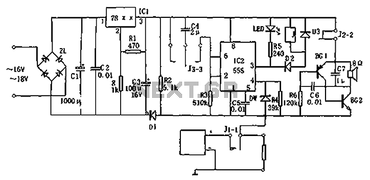
Circuit diagram for a DC power supply protection circuit. The device includes a buck rectifier power supply, a monostable delay circuit, a relay control circuit, and an audio feedback oscillation circuit. The entire circuit operates with a DC voltage...
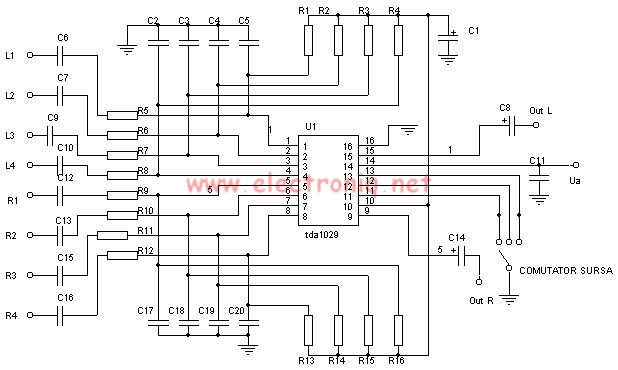
The TDA1029 is a dual operational amplifier configured as an impedance converter. Each amplifier features four mutually switchable inputs that are safeguarded by clamping diodes. Signal sources can be switched in various modes. The electronic components required for this...

More: The input data contains a brief description with no additional context or information provided. In the realm of electronics, a circuit schematic typically serves as a visual representation of an electrical circuit. It illustrates the various components such...
The circuit utilizes the CMOS 4017 decade counter integrated circuit (IC). Each press of a switch advances the output from 0 to 9. By connecting the output through an AND gate to the subsequent IC, a specific code must...
This device, available in a Stainless DIL 8 package, is capable of measuring four independent analog voltages ranging from 0 to 5 volts. It transmits the measurement results as four characters via a standard asynchronous serial link. The described device...
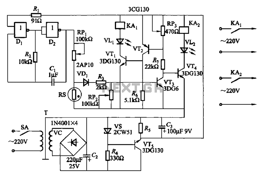
Two NAND gates (Di, Dz) and a resistor (Rz) along with capacitors (C1, etc.) form an RC self-excited multivibrator with an oscillation frequency of 2.5 Hz and an oscillation amplitude of 4 V. This circuit is used as a...