
SPI-Flash Programmer 3.7

The SPI Flash Programmer operates by interfacing with various Atmel microcontrollers, allowing for efficient programming of flash memory. The selection of the 74HCT367 IC as a buffer is critical, as it ensures that the signals from the parallel port are adequately strengthened for reliable communication with the microcontroller, particularly when interfacing with lower voltage systems. The ability to select control signals provides flexibility for different programming scenarios, accommodating a range of user requirements.
The power supply options—either a 9V DC adapter or a battery—enhance the versatility of the programmer, allowing it to be used in various environments, including portable applications. The use of the 74HCT04 IC for clock signal generation is a key feature, as it ensures that the microcontroller receives a stable clock during programming, which is vital for accurate data transfer.
In standalone mode, the programmer's connection to the microcontroller is facilitated through a breadboard or veroboard with a ZIF socket, which allows for easy insertion and removal of the microcontroller. This setup is particularly advantageous for prototyping and development, as it enables quick modifications and testing of different microcontroller configurations.
Attention must be paid to the programming of the RSTDISBL fuse in AVR devices. This fuse, when programmed, disables the ability to perform serial programming, which can complicate future updates or modifications to the firmware. Therefore, caution is advised, and a high-voltage parallel programmer may be needed to recover the programming capability if this fuse is inadvertently set.
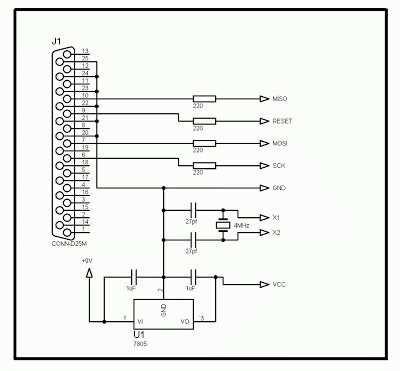
Overall, the SPI Flash Programmer is a robust tool for developers working with Atmel microcontrollers, providing essential features for both in-system and standalone programming while ensuring compatibility across different voltage levels and device types.This SPI Flash Programmer can be used either for in-system programming or as a stand-alone serial flash programmer for the Atmel SPI programmable devices. The programmer hardware interface is controlled by the PC parallel port and the parallel port control signals are freely selectable by the user.
The software supports both the 8051 and AVR serie s devices. Figure 1 shows the circuit diagram of the SPI Flash programmer hardware interface, the power to the interface is provided either by a 9V dc adapter or a 9V battery. The 74HCT367 IC buffer the parallel port signals. It is necessary to use the HCT type IC in order to make sure the programmer should also work with the 3V type parallel port.
The 74HCT04 is used to generate the clock signal for the u-controller when programming the device in stand-alone mode. Figure 2 shows the connection diagram for the stand-alone programming, the u-controller to be program is placed on a breadboard or on a veroboard with a ZIF socket, the required signals are then wired to the respective pins of the u-controller.
Also make sure do not program the RSTDISBL fuse in the AVR series devices, unless it is necessary otherwise further serial programming is disable, to restore the serial programming a high voltage parallel programmer is required. 🔗 External reference
Related Circuits
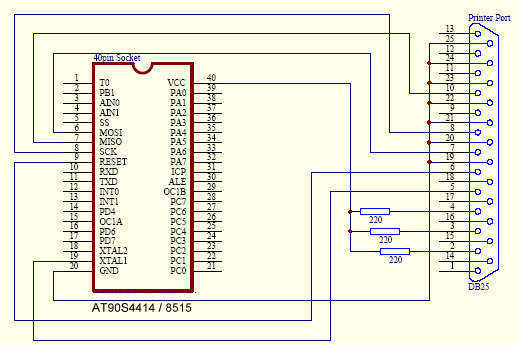
The following circuit diagram illustrates a very simple AVR microcontroller setup (source: unknown). It requires minimal components and is easy to construct on a general-purpose matrix PCB. PonyProg2000 software can be used to program the AVR microcontroller with this...
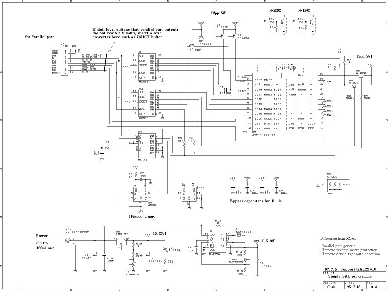
This GAL programmer is controlled via a parallel port, so that any exclusive interface is not required for the programmer. It is easy to use on the notebook PCs. When programming a PIC, a socket converter is needed. After...
To program some AVR microcontroller unit (MCU) you will need an AVR programmer. The better way to do that is to buy some development kit like STK-500. This kit has the advantage to give you serial port, LCD connector,...
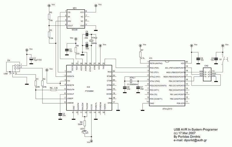
Currently, USB is the most widely used connection between PCs and peripherals, such as AVR programmers, printers, and scanners. Therefore, it became necessary to modify an old serial AVR In-System Programmer (ISP) to function with a USB connection. One...
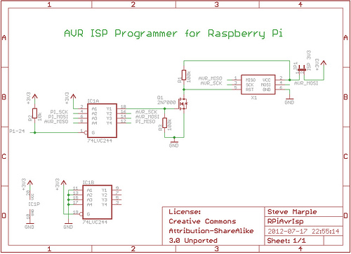
As a fully-featured Linux computer, many external programmers can be used with the Raspberry Pi to program the Atmel AVR range of microprocessors. It is also possible to utilize the general-purpose input/output lines (GPIOs) found on the Raspberry Pi...
The 5-volt microcontroller interfaces with the RS-232 serial connector and the USB-B connector. It is responsible for communicating with the checker, controlling the status LEDs, and setting the voltage for the low-voltage microcontroller. The low-voltage microcontroller operates at the...