
Radio Circuits
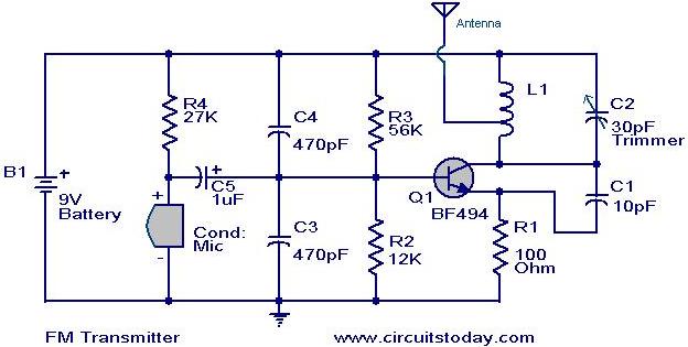
The circuit diagram for a basic FM transmitter using a transistor is also included. This design does not guarantee excellent performance or range, as it is quite elementary. The general-purpose radio frequency transistor BF 494 (Q1) is utilized for FM modulation. A condenser microphone is employed to capture sound, which is then converted into electrical variations and fed to the base of Q1 for amplification and modulation. The frequency of transmission is determined by capacitor C2 and inductor L1. The circuit can be powered by a 9V transistor radio.
Additionally, a low-cost radio circuit designed for listening to aircraft communications is described. This circuit is based on the 2N918 transistor and the 1N82 diode, operating in the 220 MHz to 400 MHz range. Capacitor C1 and inductor L1 form the tuning tank circuit, while diode D1 performs detection. Transistor T1 provides the necessary amplification, with the output audio signal being sufficient to drive small headphones.
A simple AM transmitter circuit is also presented, capable of transmitting audio to a backyard. This circuit is designed to comply with FCC regulations regarding power output while producing adequate amplitude modulation of voice in the medium wave band. The circuit consists of two main parts: an audio amplifier and a radio frequency oscillator, built around Q1 (BC109) and associated components. The tank circuit, comprising inductance L1 and capacitance VC1, is tunable between 500 kHz and 1600 kHz.
The description of a single-chip FM transmitter using the Maxim semiconductors IC MAX2606 is provided. The MAX2606 is a compact, high-performance intermediate frequency voltage-controlled oscillator (VCO) specifically designed for wireless communication applications. It features monolithic construction with low noise and low power consumption in a compact 6-pin SOT23 package. This low-noise IC includes an on-chip varicap diode and feedback capacitances, eliminating the need for external tuning components, making it ideal for portable systems. Only an external inductor is required to set the oscillation frequency, and it includes an integrated differential output buffer for driving a mixer.
Lastly, a compact and low-cost FM radio circuit using the IC TDA 7000 is described. This circuit is designed according to the data sheet and yields excellent results, making it suitable for all levels of electronic enthusiasts. The TDA 7000 is a monolithic integrated circuit for mono FM portable radios, where minimizing peripheral components is essential. It employs a Frequency-Locked-Loop system with an intermediate frequency of 70 kHz, with selectivity achieved through active RC filters. The only alignment needed is for the resonant circuit of the oscillator, which selects the reception frequency.
The direct-coupled radio circuit is an effective design for listening to nearby stations. It utilizes Q1 as both a diode detector and the first audio amplifier, with detection occurring across the first emitter-base junction.
This comprehensive description covers various circuit designs, highlighting their components, functionality, and applications in AM and FM transmission and reception. Each circuit is tailored for specific use cases, ensuring versatility for electronic enthusiasts and hobbyists.MK484 AM receiver circuit A simple AM receiver circuit based on the MK484 AM receiver IC from Rapid Electronics Ltd is shown here. MK4844 is a monolithic integrated circuit that has all the necessary sections of a AM receiver like RF amplifier, detector, AGC etc.
The IC is available in TO92 package and requires very few external compo nents. In the circuit L1 and C1 forms a tank circuit. L1 also serves as the antenna coil. The audio signals available at the pin 3 of IC1 are amplified using the amplifier built around transistor Q1. C2 is a bypass capacitor Here is the circuit diagram of the simplest FM transmitter using a transistor.
Great performance or range is not guaranteed here, because this is an elementary design. General purpose radio frequency transistor BF 494 (Q1) is used here for obtaining FM modulation. A condenser mic is used here to pickup the sound. The condenser mic converts the sound to electrical variations and this variations are fed to the base of Q1, which performs the amplification as well as modulation. The capacitor C2 and L1 determines the frequency of transmission. The circuit can be powered from a 9V transistor radio Here`s a low cost radio circuit that can be used to listen to the radio conversations between aircrafts.
The radio circuit based on transistor 2N918 and diode 1N82 receives in the 220Mhz to 400Mhz range. Capacitor C1 and inductor L1 forms the tank circuit for tuning. Diode D1 performs the detection. Transistor T1 performs the necessary amplification. The out put audio signal is just enough to drive a small headphone. For driving speakers. Circuit diagram with Parts list. Notes. Use a 45cm long wire for antenna, For L1 make 2 turns of 22 AWG magnetic wire on a 5/32 Simple AM Transmitter Description Here is the circuit diagram of a simple AM transmitter circuit that can transmit your audios to your backyard. This circuit is designed with limited power output to match the FCC regulations and still produces enough amplitude modulation of voice in the medium wave band to satisfy your personal needs.
You will love this!. The circuit has two parts, an audio amplifier and a radio frequency oscillator. The oscillator is built around Q1 (BC109) and related components. The tank circuit with inductance L1 and capacitance VC1 is tunable in the range of 500kHz to 1600KHz. These components Single chip FM transmitter Description Here`s a single chip FM transmitter circuit using Maxim semiconductors IC MAX2606.
The MAX2606 is a compact, high-performance intermediate frequency VCO specially designed for wireless communication circuits. They have monolithic construction with low-noise and a low-power operation in a compact 6-pin SOT23 packing.
Th1s low-noise IC feature an on-chip varicap diode and feedback capacitances that avoid the need for external tuning components, making the MAX2606 perfect for portable systems. Only an external inductor is needed to set the oscillation frequency. In addition to this, an integrated differential output buffer is also there for driving a mixer Single Chip FM Radio Here is a compact low cost FM radio circuit using IC TDA 7000.
This circuit is designed as per the data sheet and the result is excellent. Ideal for all category of electronic enthusiasts. The TDA7000 is a monolithic integrated circuit for mono FM portable radios, where a minimum on peripheral components is crucial. The IC TDA 7000 has a Frequency-Locked-Loop system with an intermediate frequency of 70 kHz. The intermediate frequency selectivity is achieved by active RC filters. The only function which needs alignment is the resonant circuit for the oscillator, thus selecting the reception Direct Coupled Radio Circuit Description Here is the circuit of an excellent direct coupled radio ideal for listening to near by stations.
The circuit uses Q1 as a diode detector and first audio amplifier. The detection is across the first emitter base 🔗 External reference
Related Circuits
The schematic diagram illustrates an audio stage utilizing a common-collector circuit. This configuration does not dampen the tuned circuit; rather, it enhances its response, resulting in improved sensitivity and selectivity. Due to the low supply voltage, the subsequent audio...
This page features basic, visible light photo-detector circuits that can be used to detect trains. These methods would normally be used with the photo sensor mounted between the rails. The described photo-detector circuits are designed to detect the presence of...
This document presents a collection of engaging and challenging electronic circuits that can be built for enjoyment. The author has a long-standing passion for electronics, having studied the subject since middle school and developed numerous circuits over the years....
This article compares high-side and low-side amplifiers used for measuring battery charging currents. It recommends selection criteria for current-sense resistors and describes a high-voltage circuit breaker designed for overcurrent protection. High-side and low-side amplifiers are essential components in battery management...
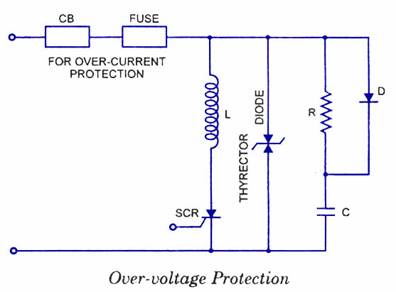
Silicon Controlled Rectifiers (SCRs) are sensitive to high voltage, over-current, and transients. To ensure satisfactory and reliable operation, they must be protected against such abnormal operating conditions. Due to the complexity and cost of protection mechanisms, devices with ratings...
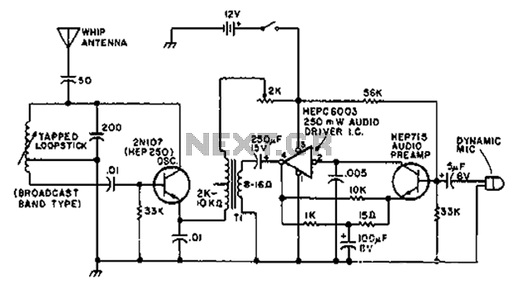
A circuit diagram of the T1 is a low-impedance output transformer, featuring a 5000-8 ohm resistor. The T1 low-impedance output transformer is designed to match the output of audio amplifiers to the impedance of loudspeakers, ensuring optimal power transfer and...
Warning: include(partials/cookie-banner.php): Failed to open stream: Permission denied in /var/www/html/nextgr/view-circuit.php on line 713
Warning: include(): Failed opening 'partials/cookie-banner.php' for inclusion (include_path='.:/usr/share/php') in /var/www/html/nextgr/view-circuit.php on line 713