
START-STOP circuit
The circuit design outlined involves a basic START-STOP drive mechanism utilizing a Nutchip microcontroller. The primary function is to control an LED using two switches: one for starting the LED and the other for stopping it. The Nutchip features two types of inputs: general-purpose and fixed inputs. The general-purpose inputs (IN1 to IN4) are programmable, allowing for customized logic states based on a truth table stored in the chip's memory.
In a typical configuration, a general-purpose input pin is normally at a high logic level (logic level 1) when left unconnected. When connected to ground (GND), the input reads as a low logic level (logic level 0). This is achieved by connecting one terminal of a switch to the input pin and the other terminal to ground. When the switch is pressed, it completes the circuit to ground, resulting in a logic level 0 being detected by the Nutchip.
The truth table programmed into the Nutchip dictates how the device responds to various input combinations. For this application, the two switches (SW1 and SW2) are connected to inputs IN1 and IN2, respectively. When SW1 is activated (pressed), it sends a logic level 0 to IN1, prompting the Nutchip to turn on the LED. Conversely, activating SW2 will send a logic level 0 to IN2, instructing the Nutchip to turn off the LED.
For testing purposes, if physical buttons are not available, a temporary solution involves using wires to momentarily connect the input pins to ground. This allows for the simulation of button presses. To start the LED, the user should connect a wire from the Nutchip pin corresponding to IN1 to ground. To stop the LED, the same procedure is followed for IN2.
Future enhancements to the circuit could include the integration of a relay to control larger loads, such as electric motors or lamps, expanding the application possibilities of the START-STOP drive mechanism. The schematic diagram for this setup would typically include the Nutchip, the two switches, the LED, and any additional components required for the relay, should it be included in future iterations.We are going to build a START-STOP drive (as commonly found in professional tools), that is a circuit with one switch to run the output (an LED in this case) and one switch to stop it. Nutchip feature two kind of inputs: general purpose and fixed inputs. General-purpose programmable inputs (namely IN1 ... IN4) work according to the truth table we program into on-chip memory. A free - not connected to anything - input is always at logic level 1. Connecting the pin to ground (GND, the negative power supply rail) an input will assaume logic level 0.
When we want to use a key (or a switch), whe connect it to an input on one side, and to GND on the other. This technique ensures a logic level 0 when the key is pressed (or switch closed) , and a logic level 1 otherwise. Inputs are an important feature because the truth table can read them, steering the Nutchip to do the appropriate actions.
Every state lists the input combinations and the state to jump to when the input conditions are meet. The schematic diagram is similar to the one shown in our previous article, with the addition of two key (SW1 and SW2) connected to inputs IN1 and IN2.
This is all we need to test the circuit; later we can add a relay in addition to the LED, in order to drive more meaningful load - like an electric motor or a lamp. But now, here it is our schematic. If you have already prepared the board for the experiment from part 1, it's only a matter of adding a copule of keys (ask your dealer for normally open buttons) to it.
The kind shown in the photo required soldering some short wire to button pins, in order to fit breadboard pits. If you don't have a couple of buttons at hand, for testing purpose you can "simulate" them touching briefly the GND pis with wire tips.
To START LED light, touch GND with the wire connected to Nutchip pin 8 (IN1); to STOP LED light, touch GND with the wire connected to pin 8 (IN2). 🔗 External reference
Related Circuits
How to create a hydrogen generator using a 555 timer circuit with Pulse Width Modulation (PWM). This PWM circuit can generate hydrogen on demand. The hydrogen generator circuit utilizing a 555 timer operates by controlling the duty cycle of the...
This easy electronic buzzer circuit is built based on a timer that operates to generate frequency. The IC timer NE555 is used as an astable multivibrator operating at approximately 1 kHz, producing a sound when powered on. The sound...
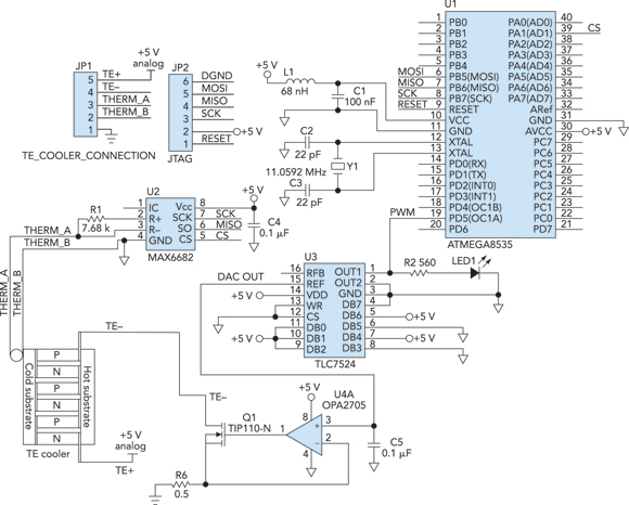
Cooling an instrument or device can enhance the signal-to-noise ratio (SNR) and extend the product's lifespan. For instance, the dark-and-noise signal of an infrared detector's output at room temperature can be significantly reduced when cooled. A custom cooling device...
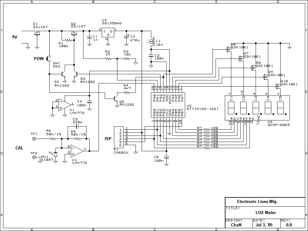
Lux meter circuit using an Atmel ATtiny26-16 microcontroller, which displays lux values on an LED display. The circuit utilizes 2SK1061 MOSFETs for driving the LEDs. The lux meter circuit operates by measuring ambient light levels and converting these measurements into...
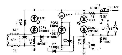
A straightforward high-power alarm driver electronic project can be developed using this circuit diagram. This high-power alarm driver project utilizes a low-power SCR to trigger a high-power SCR. When switches S2, S3, or S4 are opened or switches S5,...
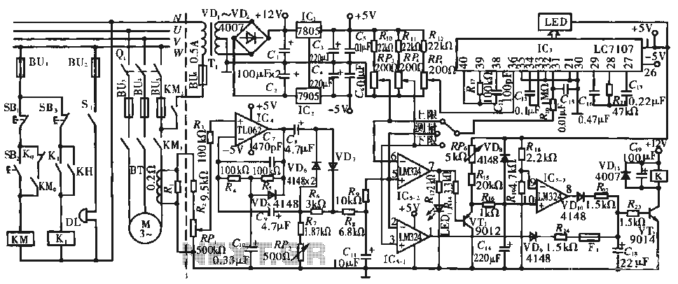
The circuit operates during standard inspection work by utilizing the voltage across resistor R2, which is connected to RP, to generate the input signal for IC4. Components R3 through Rg, along with capacitors C7 and C1, and diodes VD7...