
Starting Network for Astable Multivibrator
An astable multivibrator is a fundamental electronic circuit that continuously switches between its two states without requiring any external triggering signals. This circuit is widely used in various applications, including clock generation, signal modulation, and timing applications.
The basic configuration of an astable multivibrator typically involves two resistors and a capacitor connected to a bistable multivibrator, often utilizing operational amplifiers or transistors. The resistors control the charge and discharge time of the capacitor, which in turn dictates the frequency of oscillation.
When the circuit is powered, the capacitor begins to charge through one resistor until it reaches a certain threshold voltage, at which point the output state changes from low to high. The capacitor then discharges through the second resistor, causing the output to switch back from high to low. This cycle continues indefinitely, resulting in a square wave output.
The frequency of oscillation can be calculated using the formula:
\[ f = \frac{1.44}{(R1 + 2R2) \cdot C} \]
where \( R1 \) and \( R2 \) are the resistances in ohms, and \( C \) is the capacitance in farads. The duty cycle, which determines the proportion of time the output is high versus low, can also be adjusted by varying the resistor values.
Astable multivibrators are commonly implemented in digital circuits for applications such as LED flashers, tone generators, and pulse width modulation (PWM) signals. Understanding the design and behavior of this circuit is essential for engineers working with timing and waveform generation in electronics.A flip-flop that generates two unstable states (high-low) is called astable multivibrator, a fancy name for you to say it`s an oscillator. The very basic of.. 🔗 External reference
Related Circuits
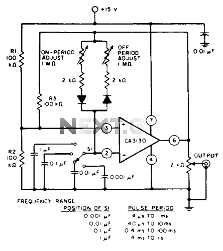
The circuit features independent control of "ON" and "OFF" periods and employs the CA3130 BiMOS operational amplifier for various applications, including filters, oscillators, and long-duration timers. It operates with an input current of 50 pA, allowing oscillators to utilize...
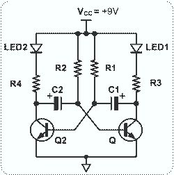
This circuit is straightforward and easy to construct, utilizing two transistors as active components along with several passive components such as resistors, capacitors, and two LEDs. The circuit employs the MPS2222 transistor, though any NPN type transistor can be...
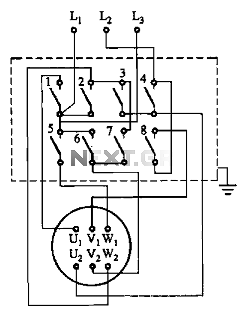
The circuit illustrated in Figure 3-36 includes the starter contact closure detailed in Table 3-1. In the figure, U1, V1, W1, and U2, V2, W2 represent the first three-phase stator windings of the motor terminals. The circuit depicted in Figure...
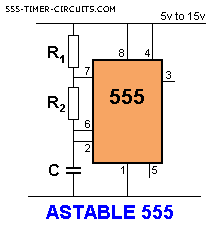
The capacitor C charges through resistors R1 and R2. When the voltage across the capacitor reaches 2/3 of the supply voltage, pin 6 detects this condition, and pin 7 is connected to ground (0V). The capacitor then discharges through...
The astable multivibrator presented in Wikipedia and college materials is depicted on the left side of the image. In contrast, the schematic on the right side is sourced from an LTSpice example. The right schematic is incorrectly drawn, and...
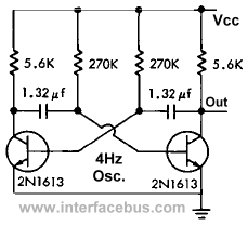
A multivibrator is a type of relaxation oscillator consisting of two stages that are coupled, with the input of one stage derived from the output of the other. Essentially, a multivibrator comprises two amplifier circuits arranged with regenerative feedback,...