
Static 0 to 9 Display using SN7446 and 7490
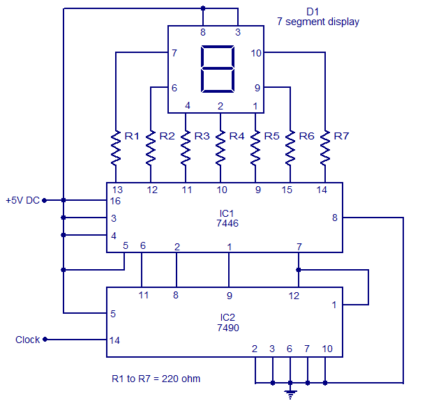
The circuit operates by clocking the 7490 IC, which is a binary-coded decimal (BCD) counter. Each clock pulse increments the counter's output, which ranges from 0000 (0) to 1001 (9). The output is then sent to the IC7446, which interprets the BCD input and translates it into signals that illuminate the appropriate segments of the seven-segment display.
In a common anode display, the anodes of the LEDs are connected to a positive voltage supply, while the cathodes are connected to the outputs of the 7446 decoder. When the decoder activates a specific output corresponding to a digit, it connects the respective cathodes to ground, allowing current to flow through the anodes and illuminating the segments required to form the desired numeral.
The current limiting resistors (R1 to R7) are crucial for protecting the LEDs from excessive current, which could lead to overheating and failure. The values of these resistors can be calculated based on the forward voltage of the LEDs and the supply voltage to ensure that the current remains within safe limits, typically around 20 mA for standard LEDs.
Overall, this circuit is a practical and efficient way to display numerical information in a clear and visually appealing manner, suitable for various electronic projects and applications where numerical output is required.The circuit shown here is a simple Static 0-9 Display can be used in many applications. The circuit is based on 7490 asynchronous decade counter (IC2), a 7-segment display (D1), and a seven-segment decoder / driver IC 7446 (IC1). The seven-segment display consists of 7 LEDs as `a` to `g`. For different LEDs bias, we can show the digits 0 to 9. Sev en Segment Displays are of two types, the common cathode and common anode. Like the type of anode anodes of all seven LEDs are attached, while the type common cathode cathodes are all together. The seven-segment display used here is a type common anode. The resistance R1 to R7 are current limiting resistors. IC 7446 is a decoder / driver IC that is used to control the seven segment display. Work of this circuit is very simple. For each clock pulse output of IC2 BCD (7490) advances a bit. The IC1 (7446) decodes the BCD output for the form of seven segments and controlling the display to indicate the corresponding digit.
🔗 External reference
Related Circuits

Voltage regulator ICs (78xx series) provide a steady output voltage, in contrast to a widely fluctuating input supply, when the common terminal is grounded. The 78xx series of voltage regulator integrated circuits (ICs) are widely utilized in electronic circuits to...

A very simple dimmer circuit with only the essentials. In this circuit, the values are given for a BT138 at 220V AC. For 115V AC, experimentation with values may be necessary. R1 can vary from one triac to another;...
The copyright of this circuit is owned by Smart Kit Electronics. This document discusses improvements and modifications based on the original schematic. It describes a straightforward yet highly accurate and useful digital voltmeter designed as a panel meter, suitable...
Build a large dancing robot. This was intended to be a walking robot, but it ended up moving in a more rhythmic manner. A video is available in the last step. The project involves the construction of a large dancing...
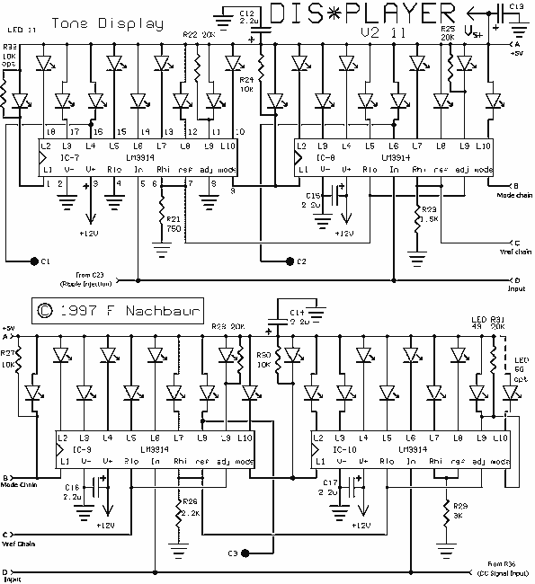
The heart of the circuit is the tone (pitch) display section, based on the popular LM3914 display driver. This device drives ten LEDs in a linear display, with programmable endpoints and the choice of "dot" or "bar" modes of...
This circuit detects the presence of electrostatic fields by using a Field Effect Transistor (FET) to alter the flash rate of two Light Emitting Diodes (LEDs). The FET is installed in the timing circuit and causes a change in...