stealth action laser tripwire system

This project allows the creation of a security system that employs a laser tripwire mechanism. When the laser beam is interrupted, an audio alarm, generated by a 110dB piezo personal alarm, is activated. The system emits three beeps upon interruption, and if the beam remains broken after the third beep, the alarm sounds. This system is most effective in confined spaces where movement is restricted, making it difficult for an intruder to bypass the tripwire. The project utilizes a PIC microcontroller (12F629) and requires basic electronic skills for assembly and modification. The system calibrates itself upon power-up, lighting an LED to indicate its active state. If the beam is broken, the LED lights up and the beeping sequence begins. The system also features a DISABLE function that can be activated by a sharp impact, allowing for modifications using an Airsoft gun or similar devices.
This laser tripwire security system is designed to provide an effective deterrent against intruders. The primary components include a laser pointer, a light sensor, a PIC microcontroller (12F629), and a 110dB piezo alarm. The laser pointer serves as the source of the beam, while the light sensor detects interruptions in the beam. The PIC microcontroller is programmed to manage the system's operation, including the calibration process and the alarm triggering sequence.
Upon powering up, the system calibrates itself by detecting the laser light. The LED indicator provides visual feedback during this process. Once the calibration is complete, the system enters an active state, indicated by a slow heartbeat blink of the LED. If an intruder breaks the laser beam, the light sensor detects the absence of the laser light, prompting the PIC to initiate a sequence of three rapid beeps. If the intruder does not restore the beam within this time, the alarm is triggered, alerting to the breach.
The design includes a modification option that allows the alarm to be disabled through a physical impact. This is achieved by connecting a piezo element to a piece of polycarbonate. When this sheet is struck, such as by a BB from an Airsoft gun, the piezo element generates a signal that pulls the DISABLE pin on the PIC low, effectively disabling the alarm system. This feature adds a layer of versatility to the system, allowing for creative engagement with the device.
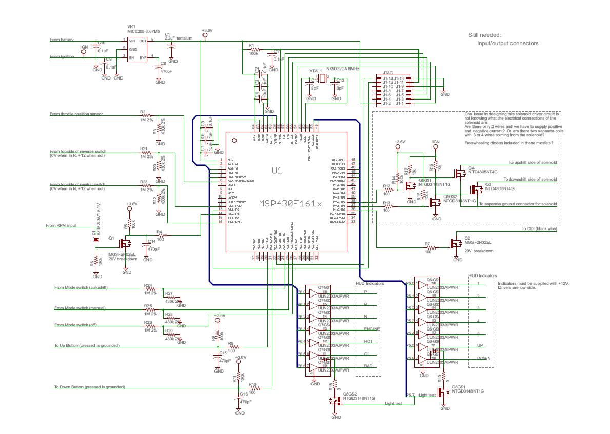
The construction of this system requires an understanding of basic electronics, including concepts such as regulated voltage and pull-up resistors. The schematic provided with the project outlines the necessary connections and components required for assembly. Careful attention to these details will ensure the successful operation of the laser tripwire alarm system. This project is ideal for individuals with a foundational knowledge of electronics who are looking to build an engaging and functional security system.With these, you can make your very own security system that gives intruders a sporting chance! It`s the laser-version of saying But before I kill you, Mister Bond This laser tripwire system will trigger an audio alarm (made from a 110dB piezo personal alarm from the 1$ store) when something breaks the laser beam, which is provided by a si mple laser pointer. What makes this Hollywood-style is that when the beam is broken, the unit Beeps three times. If the beam is STILL broken after the 3rd beep, the alarm sounds. (If the intruder backs off and unbreaks the beam before the 3 beeps are over, the alarm does not sound). These are best used when placed somewhere that is physically confining, like around tight or low spaces so an intruder cannot simply run through all the tripwires.
Any area that constricts movement is ideal. For example, the tripwires which require the intruder to quickly break contact to avoid and alarm can work well in conjunction with the Hollywood-style motion sensors, which require the intruder to STOP moving to avoid an alarm! This project uses some electronics and a PIC (12F629). If you own or have access to a PIC programmer (and know how to use it!) you will be able to make and modify this project as long as you possess basic electronic skills.
If things and terms like regulated voltage, HEX files, and pullup resistors don`t mean anything to you then you will have problems if you try to make this project. The laser tripwire alarm assumes the light sensor is being lit by a laser when it is powered up. It will attempt to calibrate itself at powerup. Power up the alarm, and when the LED is blinking quickly, break the beam. When the LED lights solid, unbreak the beam. The LED will turn off and begin a slow heartbeat blink. The sensor is now active. If the laser beam is broken (and the laser stops hitting the light sensor) the LED will light up and the unit will emit 3 beeps in rapid succession.
If this beam is STILL broken at the end of the 3rd beep, the alarm will sound. This allows someone who touches a laser beam to back off to avoid an alarm. The laser tripwire`s PIC has been programmed to use a RESET and DISABLE input, same as the Hollywood Motion Sensor. That means that with the right modification you can make the unit shootable (really just a fancy way of hitting the DISABLE switch).
If you own an Airsoft gun, you can make the sensor shootable by connecting a piezo element and a small sensor circuit to a small piece of plexiglass/lexan/polycarbonate and feeding the output into PIN 5 (DISABLE) of the PIC. The sensor will be disabled if the sheet of polycarbonate is shot. The sharp impact from the BB hit will transfer into the piezo element (superglued to the sheet of polycarbonate) which will trigger the DISABLE input of the motion sensor circuit.
(This was only made with Airsoft guns in mind. If you own a Laser Tag gun, you`ll need to roll your own sensor for detecting a shot . If you`re using a paintball gun, you`re probably better off actually shooting a switch with a target on it to trigger the Disable input, since paintballs carry a lot of Oomph to them and can easily trigger a beefy switch. Also paintball hits are messy, so keep that in mind. Finally, if you`re using a real gun well, I think any way you slice it the disabling of the device will be permanent in that case.
) This modification assumes you have the electronics knowledge to follow the schematic below. The circuit shown will pull the /Disable pin on the PIC low when the piezo element detects a sharp and strong impact on the polycarbonate plate it is bonded to. This is not a foolproof system, but it seems to work fine on my workbench with a spring-powered USP and it uses very few parts.
Your mileage will probably vary. This is a brief video demonstrating the basic operation of the completed prototype. It demos the triggering of the alarm as well as backing o 🔗 External reference


