
Step-Down Converter Controller
The TPS6420x controller is a versatile DC-DC step-down converter designed for applications requiring efficient voltage regulation from various input sources, including series-connected battery cells and USB power supplies. It is capable of delivering a stable output voltage of 3.3 V with a maximum output current of 2 A, making it suitable for microcontroller-based systems and similar electronic devices.
This controller operates efficiently across a wide range of output voltages, which can be configured through the selection of external components such as inductors, P-channel MOSFETs, and Schottky diodes. The low quiescent current in power-down mode (100 nA) and under no-load conditions (20 mA) enhances its suitability for battery-powered applications, allowing for extended operational life.
The TPS6420x can directly connect the output to the input when the input voltage is equal to or lower than the desired output voltage, simplifying the design and reducing component count. The output voltage can be adjusted from 1.2 V up to the input voltage level, facilitating flexibility in various applications.
As an asynchronous converter, it employs a unique control scheme that maintains constant on-time and off-time during operation, differing from conventional PWM and PFM methods. This allows the controller to adapt its switching frequency based on load conditions, optimizing efficiency across a range of operating scenarios.
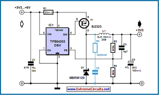
The circuit configuration includes a classical step-down topology with an input voltage range of 3.3 V to 6 V. The optional 33 m shunt resistor serves as a current limiting feature, ensuring safe operation within specified limits. The TPS64202 variant provides selectable minimum on-times (ranging from 1.6 ms to 0.2 ms) and a fixed off-time of 300 ns, allowing for precise control over the switching behavior.
In discontinuous conduction mode (DCM), the controller manages low output currents effectively, with the inductor current cycling between zero and a maximum threshold. The Schottky diode plays a critical role in managing the energy in the inductor, resulting in oscillations that do not compromise converter efficiency. An optional RC damping network can be employed to mitigate these oscillations if desired.
At higher output currents, the converter operates in continuous conduction mode (CCM), where the inductor current remains above zero, maintaining a direct relationship between output voltage and the duty cycle of the switching signal. Alternate P-channel MOSFETs, such as the IRLML6401 and IRLML6402, can be utilized if the preferred Si2323 is unavailable, albeit with some trade-offs in on-resistance and gate capacitance.
For the Schottky diode, the MBRM140 is suggested as an alternative, although it features a slightly higher voltage drop than the recommended MBRM120. The TPS6420x family of devices is produced by reputable manufacturers, including IRF and ON Semiconductor, ensuring reliability and performance in electronic applications.The TPS6420x controller is designed to operate from one to three series-connected cells or from a 3. 3 V or 5 V supply obtained from a USB port. At its output it can produce 3. 3 V at 2 A, suitable for powering a microcontroller-based system. With a suitable choice of external components (inductor, P-channel MOSFET and Schottky diode) the device can be operated over a wide range of possible output voltages and currents. A further advantage is its extremely low quiescent current consumption in power-down mode (100 nA typical) and in no-load operation (20 mA). Also, if the input voltage is less than or equal to the desired output voltage, the device can connect the output directly to the input.
Using just a few external components the TPS6420x can cover an output voltage range from 1. 2 V up to the input voltage at up to 3 A, as long as a suitable P-channel MOSFET and Schottky diode are used. The device is an asynchronous step-down converter which, unlike the more widely-used PFM (pulse-frequency modulation) and PWM (pulse width modulation) types, involves a constant on-time and/or constant off-time.
Conventional controllers operate in PWM mode at medium to high loads, switching to PFM at lower loads in order to minimise switching losses. The controller described here also adjusts its switching frequency in accordance with the load to achieve a similar effect to the PFM/PWM controllers.
The circuit diagram shows a classical step-down converter with an input voltage range from 3. 3 V to 6 V and an output voltage of 3. 3 V at a current of up to 2 A. The optional 33 m shunt resistor provides for current limiting. The TPS64202 offers a minimum on-time selectable between 1. 6 ms, 0. 8 ms, 0. 4 ms and 0. 2 ms and a fixed off-time of 300 ns. A MOSFET in the supply voltage path is switched on by the controller for as long as is necessary for the output voltage to reach its nominal value, or until the maximum permissible current, as determined by the shunt resistor, is reached. If the current does exceed this limit the MOSFET is switched off for 300 ns. If the nominal output voltage is reached, the MOSFET is switched off and remains in the off state until the output voltage once again falls below the nominal value.
At very low output currents the controller therefore operates in discontinuous mode` (DCM). Each switching cycle begins with the current at zero. It rises to the threshold or maximum value, and then falls again back to zero. At the moment of switch-off the Schottky diode causes the residual energy in the inductor to appear as a quickly-decaying oscillation at the resonant frequency of the output filter. This low-energy oscillation in discontinuous mode is normal and has no adverse effect on the efficiency of the converter.
It can be damped using the (optional) RC series network. At higher output currents the switch-down converter operates in continuous conduction mode (CCM). In this mode the inductor current never falls to zero. The output voltage is directly proportional to the switching mark-space ratio in this mode. If the Si2323 P-channel MOSFET from Vishay-Siliconix is not available, the IRLML6401 (12 V type) or IRLML6402 (20 V type) from IRF can be used instead. Both these types have a higher on resistance, but do offer a lower gate capacitance. An alternative for the Schottky diode suggested is the MBRM140 (available from Digi-Key and Farnell), although this is in an SMB package rather than the Powermite package of the MBRM120.
The voltage drop at 1 A is somewhat higher: 0. 6 V instead of 0. 45 V. The devices are manufactured by IRF and ON Semiconductor. 🔗 External reference
Related Circuits
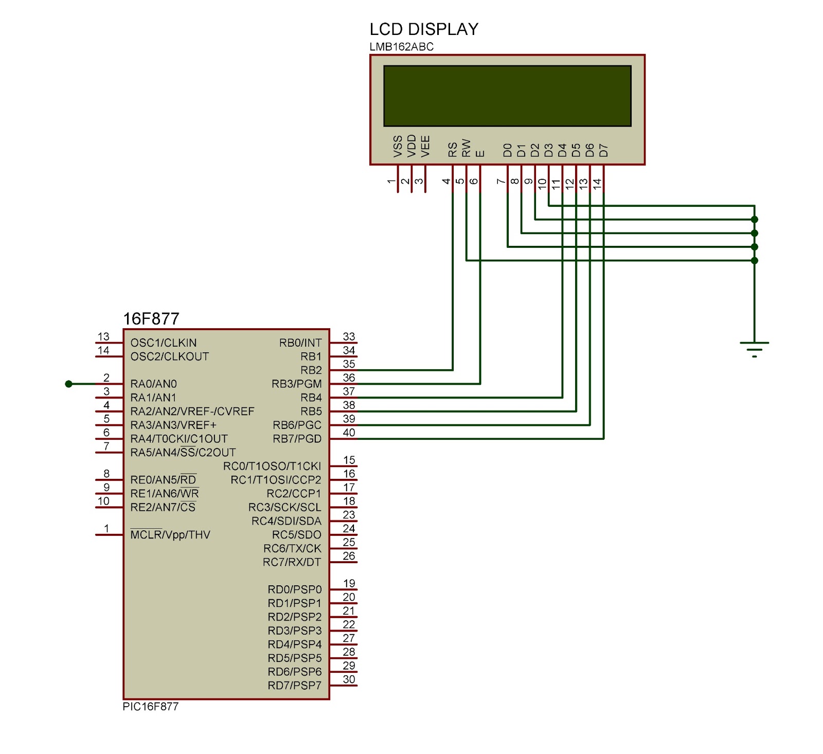
This document outlines the connection of a 16x2 LCD display to a microcontroller, specifically the PIC 16F877A. The circuit diagram is provided, although power supply and oscillator connections for both the PIC and LCD are not depicted. The LCD...
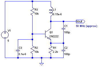
The core of any transmitter is typically an oscillator circuit, and in simple transmitters, such as QRSS devices, a crystal is often used. Frequency adjustment is achieved by modifying the capacitance to ground on one of the crystal's legs....
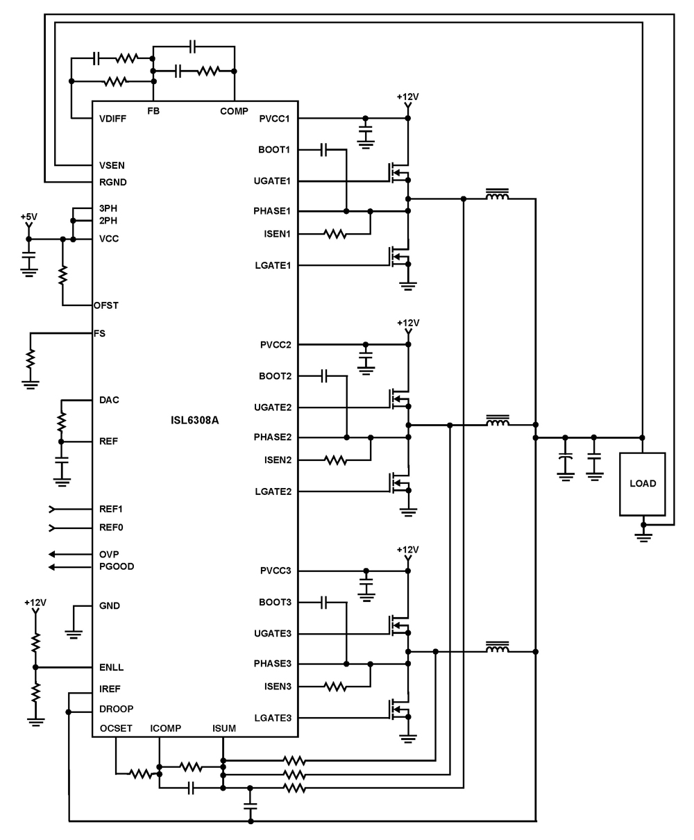
The ISL6308A is a three-phase PWM control integrated circuit (IC) equipped with built-in MOSFET drivers. It delivers precise voltage regulation suitable for various applications, including high current low voltage point-of-load converters, embedded systems, and other general low voltage medium...
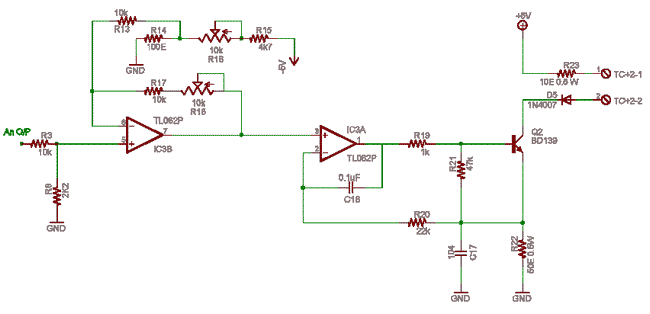
Ensure a ±5V dual supply for the TL062 operational amplifier (IC3). The ground is shared as the power supply ground, allowing grounds to radiate from the ground plane on one side of the PCB. Resistors R3-R8 form an attenuator...
Normally, an analog-to-digital converter (ADC) requires interfacing through a chip to convert analog signals into digital format. This necessitates both hardware and software, resulting in increased complexity and overall cost. The circuit presented here is configured around the ADC...
This integrated circuit is highly efficient and does not require any external glue logic for operation. It features two pins to control a motor: one for direction and the other for stepping pulse triggers. The design is compact and...