
Stepper Motor Controller
With this circuit, the speed of the engine is controlled. When the situation at the foot RB7 is logical 1 (High), the transistor TR1 conducts. In this case, the capacitor C1 will discharge through the transistor TR1, and the tendency to extremes becomes 0 V. When the situation at the foot RB7 is logical 0 (Low), the transistor stops conducting, current passes through the potentiometer VR1, the resistance R4, and charges the capacitor C1. The logical 1 (High) at node R4 and C1 is detected by the foot RB5, as soon as the situation in RB7 is logical 0 (Low). The lower the resistance of potentiometer VR1, the shorter the charging time of capacitor C1. The engine speed diminishes as the resistance of VR1 increases, making the engine speed inversely proportional to the resistance value of the potentiometer VR1.
This circuit determines if the motor will rotate counterclockwise or clockwise if it stops. A switch button and a pull-up resistor are connected to the foot RB5. The foot RB has the ability to use the internal chip resistors pull-up, but because the foot RB5 detects voltage that is logical 1 (High), it was considered safer to use an external pull-up resistor.
For the timing of the processor, a ceramic filter (resonator) or 4-MHz crystal and two 22pF ceramic capacitors are used.
The purpose of the feeder circuit is to provide a constant voltage of 5V for the operation of the PIC when the voltage of the motor is greater. In this example, the operating voltage of the engine is 5V, and the output voltage of the power supply is also +5V. The trend now is that fueling the PIC is about one volt less, but this is not a problem because the PIC16F84A has an operating voltage range of 2V to 5.5V, so a 5V, 100-mA stabilizer is sufficient.
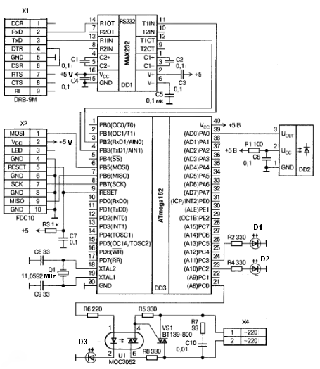
The circuit can be divided into several functional blocks: the Darlington driver stage, the speed control circuit, the direction control circuit, the timing circuit, and the power supply circuit. The Darlington driver stage utilizes the 2SD1209K transistor to efficiently drive the stepper motor coils, leveraging its high current gain to achieve rapid switching and minimize power loss. The protective diode across each coil safeguards against back EMF generated when the motor is switched off, ensuring reliability.
The speed control circuit employs a capacitor (C1) and a potentiometer (VR1) to modulate the charge time, thus controlling the motor's speed. The feedback mechanism through the RB5 pin allows for real-time adjustments based on the charging state of the capacitor, making the system responsive to user inputs.
The direction control circuit, utilizing an external pull-up resistor, ensures that the motor's rotation direction can be safely determined without relying solely on internal pull-up resistors, which might not guarantee the desired logic levels under all conditions.
The timing circuit, incorporating a ceramic resonator or crystal, provides stable clock signals necessary for the microcontroller's operation, contributing to the overall accuracy and performance of the circuit.
Lastly, the feeder circuit is designed to ensure that the microcontroller receives a stable voltage supply, allowing it to function correctly even when the motor operates at higher voltages. This design consideration enhances the robustness of the circuit, ensuring reliable operation across varying load conditions.This circuit leads palmorefmata coils,, engine. Each coil is driven by a transistor type Darlington. Darlington Transistors internally comprise two transistors connected in series. The "hfe" Darlington is equal to the multiplication of "hfe" of both its internal transistor. The Darlington 2SD1209K used in the circuit is "hfe" greater than 4000. Because the ratio of power input / output is high, the rising and descending front of the driving pulse can be steep. To protect the transistor from voltage spikes placed in parallel with each coil and a diode reverse polarized.
When the transistor switches from a standard conductivity in the coil of the stepper motor displays current flow which creates a high voltage, this trend means eliminated the protective diode. Speed ??control circuit With this circuit is to control the speed of the engine. When the situation at the foot RB7 be logical 1 (High), the transistor TR1 conducts. In this case, the capacitor C1 will discharge means of the transistor TR1, and the tendency to extremes becomes 0 V. When the situation at the foot RB7 be logical 0 (Low), the transistor stops conducts, current passes through the potentiometer VR1, the resistance R4 and charge the capacitor C1.
For more information on the charging and discharging click here: "Circuit R / C". The logical 1 (High), node R4 and C1, is detected by the foot RB5, as soon as the situation in RB7 be logical 0 (Low). The lower the resistance of potentiometer VR1 another so diminished and the charging time of capacitor C1.
The engine speed diminishes as the resistance of VR1 increases, so the engine speed is inversely proportional to the resistance value of potentiometer VR1. Circuit starting rotation or pause This circuit determines if the motor will rotate counterclockwise or clockwise if it stops.
A switch button and a Pull-up resistor connected to the foot RB5. The door RB has the ability to use the internal chip resistors Pull-up, but because the foot RB5 detect voltage that is logical 1 (High), it was considered safer to use an external resistor Pull-up. Timing Circuit For the timing of the processor used a ceramic filter (Resonator) or 4-MHz crystal and two 22pF ceramic capacitors Feeder circuit The purpose of the feeder is to provide a constant voltage of 5V for operation of the PIC when the voltage of the motor is greater.
Because in this example, the operating voltage of the engine is 5V, the output voltage of power supply is also +5 V. The trend now is fueling the PIC is about one volt less, but no problem because the PIC16F84A has operating voltage range 2V to 5.5V, so a stabilizer 5V 100-mA is enough.
🔗 External reference
Related Circuits
Diode D1 and resistor R1 provide VDD isolation during the programming of 24-pin devices. Jumper J3 must be shorted for 24-pin devices and left open for programming 28-pin devices. The following EEPROMs are pin compatible with their EPROM versions. In...
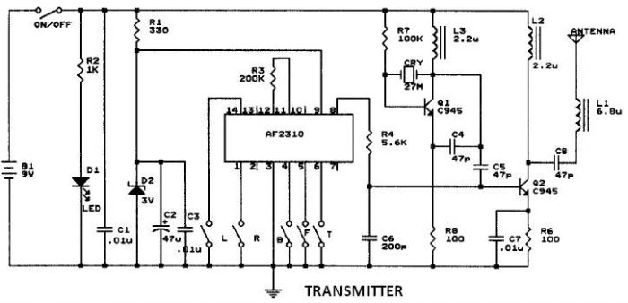
This circuit resembles that of a car radio-controlled toy with seven control functions: forward, forward-left, forward-right, backward, backward-left, backward-right, and stop. Additionally, this radio frequency circuit can be utilized for other electronic circuits that require a simple wireless motor...
The add-on circuit presented here is useful for stereo systems. This circuit has provision for connecting stereo outputs from four different sources/channels as inputs and only one of them is selected/connected to the output at any one time. When...
An IR remote control is a widely used device found with televisions, VCRs, and home theaters. It can also be utilized to control personal devices such as lights and air conditioning. Remote controls operate using infrared (IR) light, which...
The YouTube video below demonstrates the quick and easy setup of the system at the launch site. The provided description indicates a focus on the efficiency of system installation at a launch site, as showcased in a YouTube video. In...

Personal safes are innovative locking storage solutions that open with a simple touch of a finger. These devices are designed as secure storage options for medications, jewelry, firearms, documents, and other valuable or potentially hazardous items. They employ fingerprint...