
Stepper Motor Driver
This could be easily rep laced by another method such as transistors controlled by a PC`s parallel output port. Speed control is by means of a potentiometer but the circuit could accept pulses or controls from other sources such as a push button or a simple computer interface. The direction could also be controlled by a computer interface. This web page uses integrated circuits from the SN74LSxx family of TTL devices. It is not the purpose of this page to provide detailed explanations of how these devices work and an understanding of simple logic circuits would be helpful.
N. B. - Due to the lack of error detection or correction this circuit should not be used for application that require accurate step control or positioning accuracy. The circuit is intended for hobby use only. A testing version is shown near the end of this page. It is laid out differently and shows the SN7474 in logic block form and LED`s are used to indicate the motor coils being switched.
Each time the CLOCK pulse goes positive the HIGH state at the SN74194`s OUTPUT terminals, (PIN`s 12, 13, 14, 15), is shifted either UP or DOWN. Refer to the "Stepper Motor Driver Waveforms" diagram. The direction of this shifting is controlled by switch S2. When S2 is in the center OFF position the HIGH output state will remain in its last position and the motor will be stopped.
The pulses from the OUTPUT`s of the SN74194 are fed to four segments of the ULN2003 Driver. When a segments input is HIGH the transistor will turn ON and its OUTPUT will conduct current through one of the motors coils. The following diagram shows the Stepper Motor Driver circuit with its circuit boards external connection terminals.
The motor coils have been omitted from the diagram. The ULN2003 integrated circuit is a 7 Unit, Darlington High Current, High Voltage Peripheral Driver. Its outputs can handle currents of up to 500 milliamps and voltages up to 50 volts. The following diagram shows the stepping order of the inputs to ULN2003 Peripheral Driver for forward and reverse motor directions. Pin numbers are not indicated as this depends on the PCB layout. There are some links to other stepper motor related web pages further down the page. These may be helpful in understanding stepper motor operation and control. With the parts values shown on the schematic and capacitor C1 being 1uF. If resistor R1 is set to "ZERO" ohms the calculated CLOCK frequency will be approximately 100Hz and the motor will make 100 steps per second.
This CLOCK frequency will be slow enough for most motors to operate properly. The maximum RPM at which stepper motors will operate properly is quite low and the torque the motor can produce drops of rapidly as motor speed increases. Testing may be needed to determine the minimum values for R1 and C1 to produce the maximum CLOCK INPUT frequency for any given motor.
Data sheets, if available, will also help determine this frequency. There is no minimum step speed at which stepper motors cannot operate. Therefore, in theory, the values for R1 and C1 can be as large as desired. There are practical limitations to these values though and the 555 timer data sheet should be consulted for more information. Provision has been made on the printed circuit board to change the values of R1 and C1 through external connections.
It will also be possible to inject CLOCK pulses through these connections for external step control. In the above items the "calculated" minimum and maximum CLOCK frequencies are valid for the actual parts values shown. Given the tolerances of real components and the leakage currents of e 🔗 External reference
Related Circuits
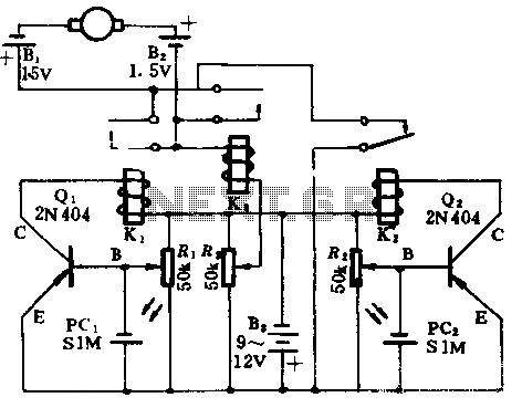
In the absence of light, photocells PC1 and PC2 exhibit high resistance, causing transistors Q1 and Q2 to remain off, which prevents the relay contacts K1 and K2 from closing. The battery B3 is connected through a potentiometer Rs,...
The LWDAQ Driver (A2037) is a Long-Wire Data Acquisition (LWDAQ) Driver. An introduction to the LWDAQ can be found in the LWDAQ User Manual. The A2037 features eight LWDAQ driver sockets, which can be connected to either a LWDAQ...
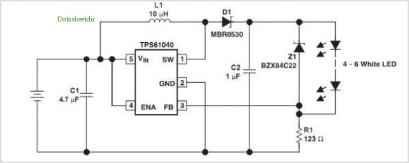
Many consumer products that utilize white light LEDs for illumination and backlighting offer gradual LED illumination during both turn-on and turn-off phases. This gradual illumination is typically achieved through a microprocessor that provides PWM dimming control. However, the following...
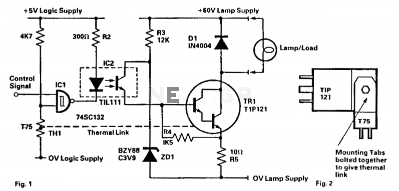
This circuit is designed to drive filament lamps with a nominal rating of 200 mA at 60 V DC using a CMOS logic signal. The lamp or load is connected in series with the Darlington transistor TR1 and an...
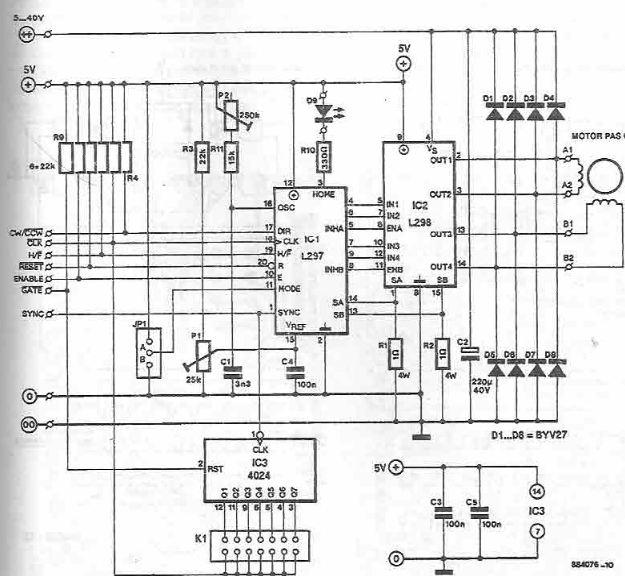
The L297 and L298 integrated circuits manufactured by SGS Thomson (ST) can be utilized to create a control circuit for a stepper motor, accommodating both two-phase bipolar and unipolar four-phase configurations, with a maximum current rating of 2 A...
The principles of DC motors are discussed in the beginner and intermediate sections of this tutorial. This section will address the electronics required to interface them with a Basic X microcontroller or other digital chips. The simplest method of...