
BA5173 HT7706 dimming control ASIC
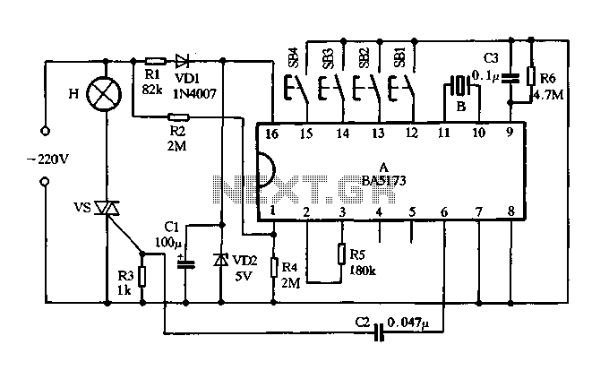
The circuit described is a half-wave rectifier configuration designed to convert alternating current (AC) into direct current (DC), specifically targeting a 5V output suitable for powering various electronic devices. The use of diodes VDI and VD2 ensures that only one half of the AC waveform is utilized, effectively rectifying the input signal.
Resistor R1 plays a crucial role in limiting the current through the circuit, thereby protecting the diodes from excessive current that could lead to damage. The capacitor C1 serves to smooth out the rectified output, reducing voltage ripple and providing a more stable DC voltage to the load.
Resistor R2 is critical in generating an AC zero-crossing signal, which can be used for synchronization purposes in applications where precise timing is necessary. This feature is particularly useful in systems that require phase control or timing adjustments.
R5, as the external oscillator resistor, is essential for generating the required frequency for the manifold's operation. This resistor helps to establish the oscillation characteristics, ensuring that the manifold operates efficiently within its intended parameters.
The combination of R6 and capacitor C3 is employed to manage the timing and reset functions of the power blocks. This integration is vital for maintaining the operational integrity of the circuit, ensuring that each power block can reset and initialize correctly after each cycle.
The circuit includes a user interface through switches SB1 to SB4, which provide various dimming options and operational modes. These switches allow for stepless dimming, enabling users to adjust brightness smoothly, while the four-step dimming feature provides preset levels of brightness for convenience. The off-delay function allows users to set a timer for the light to turn off after a specified duration, and the automatic cycling feature enables the light to operate in a repeating on-off cycle, enhancing usability in different scenarios.
Overall, this circuit design offers flexibility and control for managing lighting and power supply applications, making it suitable for various electronic projects.FIG VDI, VD2, Rl and Cl form resistance voltage half-wave rectifier circuit, the output DC voltage 5v supply manifold with electricity. R2 for the manifold provides AC zero-cro ssing signal. R5 is manifold external oscillator resistor. R6 and C3 to ensure the integration task to achieve clear reset each power block. SB1 ~ SB4 are the stepless dimming, four stepper dimming, off delay and automatic cycle switch light touch of a button, readers can choose one or four keys are used according to their needs any.
Related Circuits
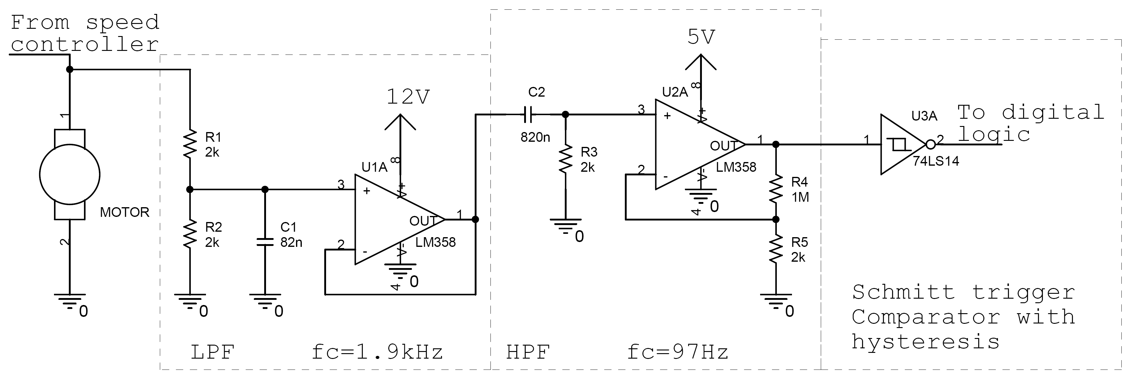
Controlling the speed of a motor is crucial in various applications, particularly in robotics. Numerous techniques exist for adjusting motor speed, each offering distinct advantages and disadvantages. This document outlines the construction of a motor controller that regulates the...
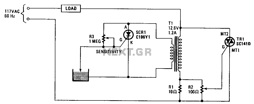
When the water level is low, the probe is out of the water, causing SCR1 to be triggered. This results in the SCR conducting and imposing a significant load on the secondary winding of transformer T1. This load is...
This circuit demonstrates that microprocessors, PCs, and modern ultra-accurate Digital-to-Analog Converters (DACs) are excessive for controlling four relays in sequence based on a control voltage ranging from 2.4 V to 12 V. By utilizing equal resistors in a ladder...

An NPN bipolar transistor is typically utilized for relay switching, particularly with 12V coil-rated relays, as it helps maintain circuit separation. A diode is also added to prevent issues. The necessity of driving the relay with a transistor depends...
.jpg)
The project outlines a method to add a cost-effective remote doorbell to an existing household doorbell system, particularly useful for individuals who may not hear the doorbell when in the basement. The household doorbell operates on a continuous 24VAC...
The image above clearly demonstrates phase angle control, where the output voltage is regulated by the gate drive signal applied to a thyristor. Phase angle control is a technique of pulse width modulation (PWM) used with alternating current (AC)...