
Strain Gage Load Cell for Thrust Measurement

The design of the strain gauge-based load cell incorporates several critical elements to ensure accurate thrust measurement in rocket motor applications. The load cell's structure is designed to minimize deflection under load, addressing issues encountered in previous designs that utilized cantilever beams. By employing a solid metal block with a strategically placed slit, the load cell effectively creates a bending beam configuration that allows for precise measurement of applied forces.
In operation, when a load is applied to the load cell, the resulting bending moment induces strain in the beam material. This strain is detected by the strain gauges, which convert mechanical deformation into an electrical signal. The use of a full-bridge configuration allows for enhanced sensitivity and noise cancellation, as the arrangement of active and passive gauges compensates for temperature variations and other external factors that could affect measurement accuracy.
Calibration of the load cell is straightforward due to the linear relationship between applied load and output signal. By applying known weights and recording the corresponding electrical output, a calibration curve can be established, enabling accurate thrust measurements during rocket motor tests. The load cell's compact design and low cost make it an accessible option for amateur rocketry enthusiasts seeking reliable thrust data without the expense of commercial load cells.
Overall, this strain gauge-based load cell design represents a practical solution for static thrust measurement in experimental rocketry, balancing performance, cost, and ease of construction. Its versatility allows it to be adapted for various thrust measurement applications, making it a valuable tool for both amateur and professional rocket testing endeavors.This web page presents details regarding the design of a strain gage based load cell that can be used, in conjunction with an electronic data acquisition (DAQ) system, for static thrust measurement of a rocket motor. The load cell described here is meant to be relatively simple to make, versatile to design with regard to load capacity, sufficientl
y accurate for its intended use, and inexpensive. The cost of a basic (single-gage) load cell made by this method would typically be no more than $10-20 USD. For a more precise four-gage loadcell made by this method, the cost would be about double this amount.
Of course, the underlying reason for constructing a load cell isn`t measured in "dollars and sense", but is part of the fundamental premise of Amateur Experimental Rocketry - the challenge to fabricate, whatever is practical, from scratch. I have made a number of loadcells using the method described here, and have utilized them extensively for thrust measurements of my motors, with excellent results.
Even for those who prefer to utilize a commercial load cell for thrust measurement, the load cell described here can be of great benefit as a "dispensible" tool for static testing of new designs (or modified designs) which inherently have a greater likelihood of catastrophic failure. With this inexpensive load cell, thrust data can be obtained on maiden firings of motors, saving the commercial unit for proven designs.
The type of load cell that is being presented is basically similar to a bending beam type. When a force is applied to the load cell, the beam (or bridge) onto which the strain gage is mounted, is subjected to combined bending and axial compressive stresses. The bending stress is by far the dominant component, hence the term "bending beam". Importantly, the relationship between the applied force and the combined stress in the beam is linear.
The stress in the beam results in corresponding strain of the beam material, and also of the strain gage (which is bonded to the surface of the beam). Strain is defined as change in length divided by the original length. The relationship between stress and strain is linear, related by the Elastic Modulus (E) of the beam material.
The electrical resistance of the strain gage is directly proportional to the strain, with the net result being that the output signal from the load cell is linearly, or directly, proportional to the applied load, simplifying calibration and use of the load cell. An important feature of the load cell is that total displacement under load is very small. This is significant, as it nearly eliminates unwanted dynamic effects associated with mass and large displacement (e.
g. spring) systems. When I originally came up with the idea of making a load cell, I wanted to simplify the construction as much as possible, while meeting certain criteria. For one thing, a compression load cell is most appropriate for thrust measurement, . Another criterion was to minimize displacement under load, as I had had a problem with my earlier Static Test Rig which had utilized a strain gage mounted on a cantilever beam.
The deflection for that system was significant enough under loading such that it proved to be necessary to add a hydraulic damper to eliminate oscillations. What eventually evolved was the concept shown in Figure 1. The load cell consists of a block of metal (steel, alumininum or brass) with a single hole drilled through it.
To generate the required bending strain, a slit is cut on one side to create a bending bridge on the opposite side, to which one or more strain gages are bonded. Two gages mounted side-by-side provide double the output signal (and thus double the sensitivity and resolution) of a single gage.
A "full-bridge" (or Wheatstone bridge) arrangement uses a total of 4 gages, of which 2 "active" gages measure the strain, and 2 "passive" gages, which serve to balance the bridge. This full-bridg 🔗 External reference
Related Circuits
The DS2715 is a comprehensive NiMH (Nickel Metal Hydride) smart charger solution featuring load detection, making it ideal for cost-effective applications. The DS2715 smart charger integrates several key functionalities designed to enhance the charging process for NiMH batteries. It employs...
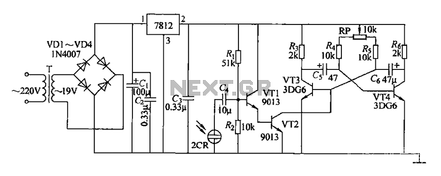
220V AC voltage is transformed by transformer T to 19V. After passing through a full-wave bridge rectifier and filter capacitor C, the voltage is regulated to DC using a 7812 voltage regulator. When the battery indicator light is illuminated,...
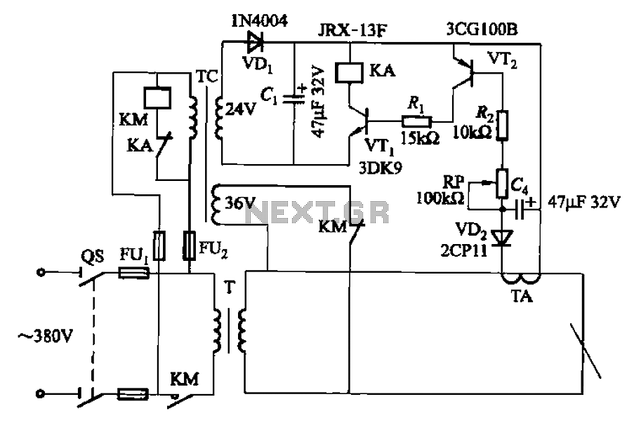
The AC arc welding machine's transistor load path for the power from the second circuit is illustrated. The figure shows a current transformer with a core cross-section of 25 mm². The transformer has a primary winding with a certain...
The LED flasher circuits below operate on a single 1.5 volt battery. The circuit on the upper right uses the popular LM3909 LED flasher IC and requires only a timing capacitor and LED. The top left circuit, designed by...
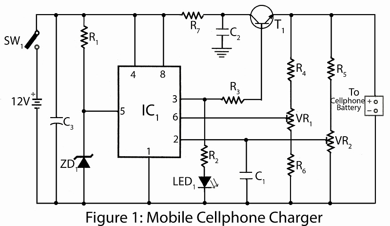
This project utilizes common electronic components to create a mobile battery charger using AA cells. The primary component of the circuit is the NE555 timer IC, which is responsible for charging and monitoring the voltage level. The control voltage...
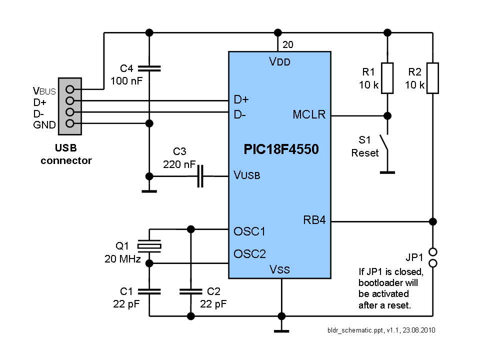
The bootloader is compatible with all USB PIC devices, including PIC18F4550, PIC18F4455, PIC18F2550, PIC18F2455, PIC18F4553, PIC18F4458, PIC18F2553, and PIC18F2458. However, since the bootloader is designed for the Microchip demo board, its configuration may not be suitable for specific projects....