
USB Bootloader

The bootloader serves as a crucial component for programming USB PIC devices, allowing for firmware updates and modifications without the need for specialized hardware programmers. The flexibility of the bootloader's source code enables customization to meet specific project requirements, such as pin assignments for bootloader mode entry or the number of status indicators used. The potential for code optimization is significant, particularly when removing unnecessary features that do not affect the core bootloader functionality.
To implement the bootloader effectively, it is essential to ensure that the project settings in MPLAB are correctly configured. This includes verifying that the path to the C18 compiler is accurate, which can be done through the project options. The removal of redundant code segments not only streamlines the bootloader but also helps in fitting the firmware within the constraints of the boot block size, which is critical for successful compilation and linking.
The design of the bootloader should also consider the operational environment of the PIC devices, including power management and state handling. For example, the bootloader must be able to distinguish between user mode and bootloader mode effectively, which may involve configuring specific pins to detect the bootloader entry condition. This configuration ensures that the device behaves as intended during the firmware update process, maintaining system integrity and reliability.
In summary, the bootloader for USB PIC devices is a versatile and essential tool that can be tailored to specific application needs, with careful attention to project setup and code optimization to ensure efficient operation.The bootloader can be used for the all USB PIC devices (PIC18F4550, PIC18F4455, PIC18F2550, PIC18F2455, PIC18F4553, PIC18F4458, PIC18F2553, PIC18F2458). Since the bootloader is designed for the Microchip demo board, the configurationof the bootloader possibly will not fit for your project.
E. g. you want to use another pin for bootloader mode entry or you do not want to spend 4 pins/LED`s for displaying the current status. Fortunately, the source code of the bootloader firmware is available. It is written in C language. It can be compiled with Microchip`s C18-Compiler, even with the free version of the compiler. In the directory USB Device - BootloadersVendor Class - MCHPUSB BootloaderBootloader - Firmware for PIC18F4550 Family Devices you find the project file MCHPUSB. mcp which has to be opened with MPLAB. In the project file the path settings point to the default C18 compiler directory c:mcc18. If you have installed the compiler in a different directroy, you have to modify the path settings in MPLAB.
To do this, select "Project - Build options - Project" from the MPLAB menu after opening the project file MCHPUSB. mcp. In this dialog go into the "Directories" tab and change the modify the Now you can build the project via "Project - Build All".
If you use the free version of the C18 compiler, the linker will fail since the generated code exceeds the boot block size. To fit the bootloader into the bootblock, we can stirp unnecessary functions from the source code, like code for showing the status of the bootloader via 4 different LEDs.
Here the code parts which can be removed without loosing bootloader functionality:. /* P R I V A T E P R O T O T Y P E S */ -> remove prototype //void BlinkUSBStatus(void);. . . void BootService(void) { -> remove call to BlinkUSBStatus //BlinkUSBStatus(); if(usb_device_state < CONFIGURED_STATE)|(UCONbits. SUSPND=1) return;. . . case UPDATE_LED: -> remove the following block /* if(dataPacket. led_num = 3) { mLED_3 = dataPacket. led_status; counter = 0x01; }//end if if(dataPacket. led_num = 4) { mLED_4 = dataPacket. led_status; counter = 0x01; }//end if */ -> add the following line counter = 0x01; break;. . . -> remove BlinkUSBStatus function /* void BlinkUSBStatus(void) { //static word led_count=0; //declared globablly instead, to save code space if(led_count = 0)led_count = 20000U; led_count-; #define mLED_Both_Off() {mLED_1_Off();mLED_2_Off();} #define mLED_Both_On() {mLED_1_On();mLED_2_On();} #define mLED_Only_1_On() {mLED_1_On();mLED_2_Off();} #define mLED_Only_2_On() {mLED_1_Off();mLED_2_On();} if(UCONbits.
SUSPND = 1) { if(led_count=0) { mLED_1_Toggle(); mLED_2 = mLED_1; // Both blink at the same time }//end if } else { switch(usb_device_state) { case DETACHED_STATE: mLED_Both_Off(); break; case ATTACHED_STATE: mLED_Both_On(); break; case ADDRESS_STATE: if(led_count = 0) { mLED_1_Toggle(); mLED_2_Off(); }//end if break; case POWERED_STATE: mLED_Only_1_On(); break; case DEFAULT_STATE: mLED_Only_2_On(); break; case CONFIGURED_STATE: if(led_count=0) { mLED_1_Toggle(); mLED_2 = !mLED_1; // Alternate blink }//end if break; default: //For POWERED_STATE and DEFAULT_STATE mLED_Both_On(); break; } }//end else of if(UCONbits. SUSPND. ) }//end BlinkUSBStatus */. . // Note: Some of the below configuration bits are commented out // to prevent build errors with some of the above listed devices.
// For example, on the PIC18F4458 CP3, WRT3, and EBTR3 don`t exist. // adjust PLLDIV configuration to your oscillator frequency #pragma config PLLDIV = 5 // (20 MHz input). . . // adjust pin to be checked for bootloader mode entry to your hardware //Check Bootload Mode Entry Condition -> adjust pin for bootloader entry if it is not RB4 pin for your hardware if(PORTBbits.
RB4 = 1) // If not pressed, User Mode { ADCON1 = temp; // Resto 🔗 External reference
Related Circuits
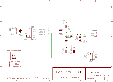
Connect any I2C client chip (such as temperature sensors, analog-to-digital converters, displays, or relay drivers) to your PC via USB quickly, easily, and affordably. Drivers are available for both Linux and Windows operating systems. The described system facilitates the integration...
Without a USB to phone battery charger circuit, charging a phone battery using a USB port on a computer can quickly damage the battery, resulting in bulging. This occurs because the voltage output from USB is 5 volts, while...
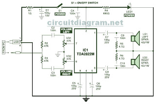
This is the circuit diagram of a USB-powered computer speaker, commonly referred to as multimedia speakers for PCs. The circuit features a single-chip design, operates on a low-voltage electrical power supply, is compatible with USB power from computers, and...
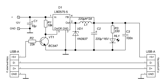
Additional power supply for USB devices. Refer to the page for an explanation of the related circuit diagram. The additional power supply for USB devices is designed to enhance the power availability for devices that may require more current than...
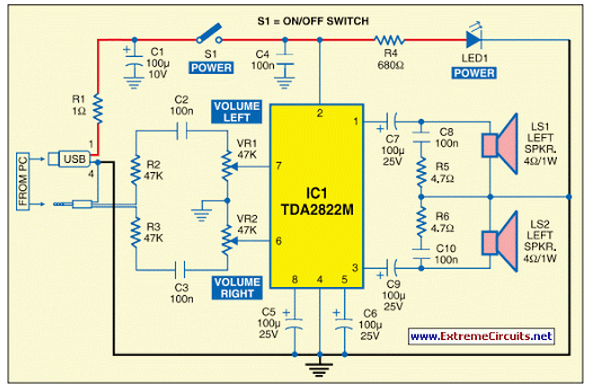
This circuit of multimedia speakers for PCs features a single-chip design, operates on a low-voltage power supply, is compatible with USB power, and allows for easy heat dissipation. The multimedia speaker circuit is designed to enhance audio output for personal...
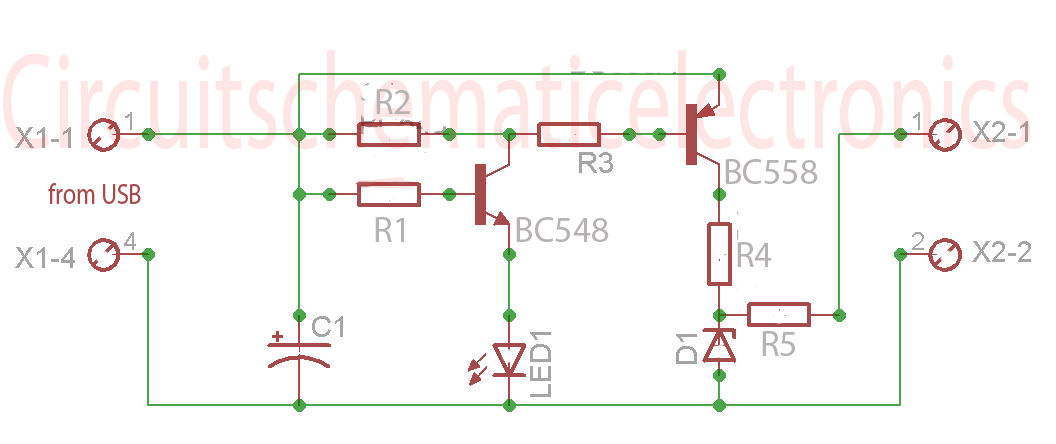
Individuals engaged in the experimentation or development of USB-connected peripheral hardware often find it frustrating to repeatedly disconnect and reconnect the plug to reestablish communication with the PC. This procedure is necessary, for instance, every time the peripheral device...