
studio ring flash xenon tubes
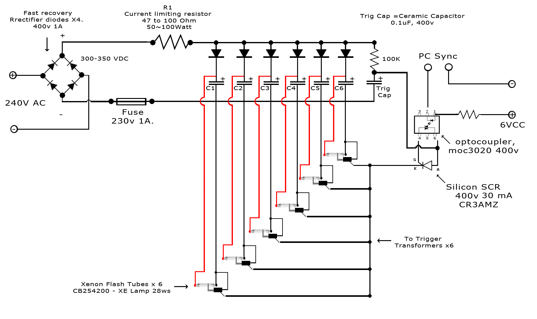
The MOC3020M is an optoisolator designed for interfacing low-voltage control circuits with high-voltage loads, making it suitable for applications where electrical isolation is required. To implement an LED indicator for capacitor charging, a simple circuit can be designed using the MOC3020M along with the 5V LEDs.
The circuit will consist of the following components:
1. **Capacitor**: This is the component whose charging status will be monitored. Select capacitors based on the required capacitance and voltage ratings for the application.
2. **MOC3020M**: This optoisolator will be employed to provide electrical isolation. The input side will be connected to the capacitor, while the output side will drive the LED.
3. **LED**: A 5V LED will be used as an indicator. It should be connected in series with a current-limiting resistor to prevent excessive current from damaging the LED.
4. **Resistor**: A resistor will be placed in series with the LED to limit the current flowing through it. The value of this resistor can be calculated using Ohm’s law, considering the LED's forward voltage and the supply voltage.
5. **Power Supply**: A 5V power supply will be used to power the LED and the MOC3020M.
The circuit operation will be as follows: When the capacitor is charging, the voltage across it will rise. Once it reaches a certain threshold, the MOC3020M will activate, allowing current to flow through the LED, thus illuminating it. This visual feedback will indicate that the capacitor is charged.
To ensure proper functionality, it is crucial to select the correct threshold voltage for the MOC3020M and to verify that the LED is rated for the intended current. Additionally, testing the circuit with a multimeter before connecting the LED can help prevent any potential damage during the live test.
This setup provides a straightforward method to visually indicate the charging status of capacitors while leveraging the existing components effectively.MOC3020M Integrated Circuit. I would love a LED to tell me when each cap is charged but I have no idea how to do that or where to put in the circuit, I have a bucket load of 5v LEDs so making use of some would be great. I have Circuit maker but dont have a spice for a xenon and cant find one anywhere so cant virtually test this circuit so its going to be a live test so I dont want to cook it.
🔗 External reference
Related Circuits
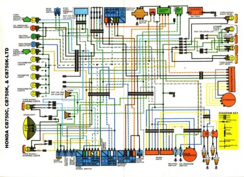
Many inquiries arise regarding motorcycle wiring, particularly among individuals attempting to repair their blinkers or seeking to streamline electronics for custom builds. A crucial aspect of constructing any chopper, bobber, cafe racer, brat bike, or rat rod involves eliminating...
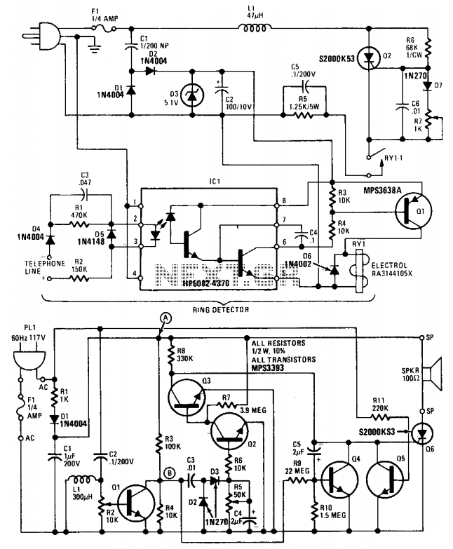
This device comprises a ring detector connected to the telephone line. When the telephone rings, the ring detector imposes high-frequency pulses on the AC power line. A receiver located anywhere on the same power line detects these pulses and produces...
This circuit is a series of electric lamp flashers. It is designed to flash a 12V bulb approximately once per second. The configuration allows Q2 and Q1 to provide biasing, eliminating the need for a resistor. Typically, a cold...
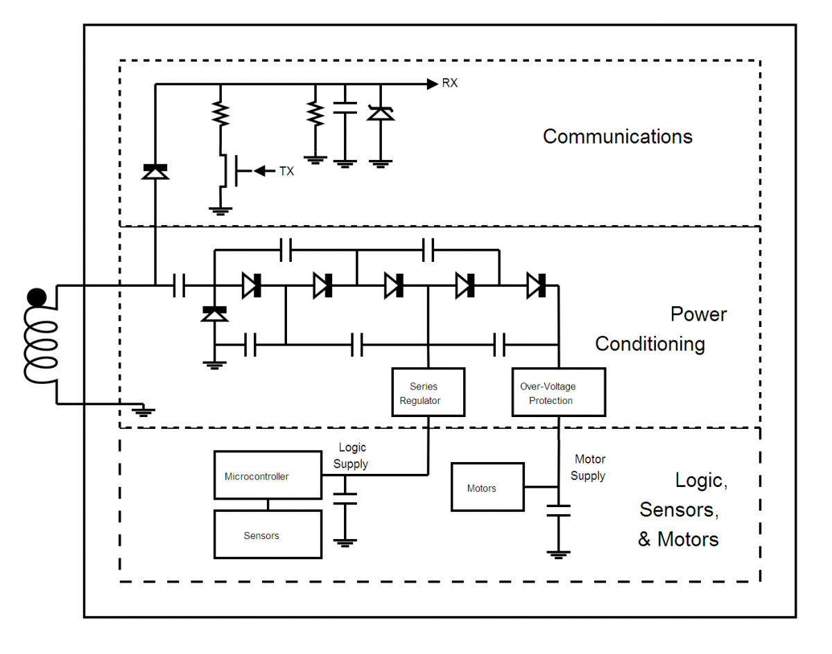
Wireless power transfer is not a new concept; it has been discussed since Tesla's patent in 1900, titled "Apparatus for Transmission of Electrical Energy" (USPTO #649, 621). As the technology evolves, the range of potential applications will expand. For...
Can anyone inform me whether the output of a monostable 555 timer circuit can be utilized to trigger another similar timer circuit? I have illustrated my concept with a... The monostable 555 timer circuit is a versatile component widely used...
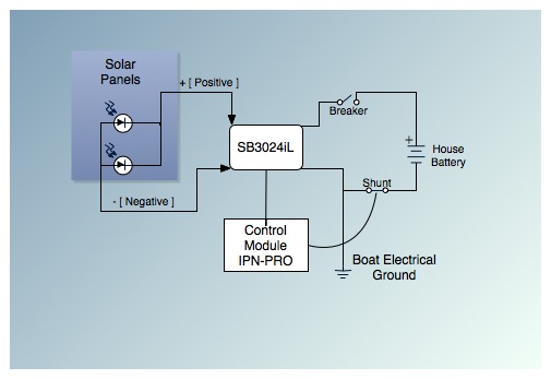
This is the fifth post in a five-part series on saving between $5,000 and $9,000 by installing a cockpit arch and a pair of solar panels on an Allied Princess ketch rigged sailboat named Aletheia. The series will continue...