
Active SubWoofer
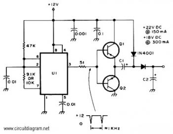
The controller circuit described operates as a signal processing unit designed to manage audio signals effectively. The inclusion of an input buffer is critical; it serves to isolate the source from the subsequent stages of the circuit, ensuring that variations in the source's output impedance do not degrade the performance of the integrator. This isolation helps maintain a consistent signal quality, particularly when integrating audio signals from multiple channels, such as left and right audio channels. The design prevents crosstalk, which can occur when signals from different channels interfere with one another, thereby preserving the integrity of the audio output.
The output stage of the controller incorporates a phase reversal switch. This feature is essential for aligning the phase of the subwoofer with the rest of the audio system. Proper phase alignment is crucial for optimal sound reproduction, particularly in multi-speaker setups where timing discrepancies can lead to audio cancellation effects, notably in the mid-bass frequencies. The ability to reverse the phase allows the user to adjust the system quickly if the mid-bass response diminishes when the level control is increased, indicating a potential phase misalignment. By switching the phase to the opposite position, the user can restore the desired audio performance.
While the controller could be simplified by eliminating certain components, such as the dual potentiometer, the current design maintains a balance between functionality and simplicity. The dual potentiometer allows for independent control of gain, which can enhance the user experience by providing more precise adjustments to the audio output level. This design consideration emphasizes the importance of maintaining a straightforward yet effective control mechanism within the audio processing circuit, ensuring that users can achieve optimal sound quality without unnecessary complexity.The controller is quite (actually very) simple. An input buffer ensures that the input impedance of the source does not affect the integrator performance, and allows summing of left and right channels without any crosstalk. The output provides a phase reversal switch, so that the sub can be properly phased to the rest of the system.
If the mid-bass disappears as you advance the level control, then the phase is wrong, so just switch to the opposite position. It turns out that the controller can be simplified, but there really is no point. While the dual pot seemed like a good idea when I built my unit, it actually only changes the gain. Now, having experimented some more, this is a very good thing, since it m 🔗 External reference
Related Circuits
The following diagram represents the schematic of an Active Tone Control circuit, commonly referred to as "ACTOR." The Active Tone Control circuit is an electronic audio circuit designed to enhance the loudness of audio signals by adjusting bass and...
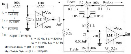
This topic continues from the more general Passive Tone Control circuit, which begins using only passive filters. This circuit follows the previous design, although the component values are different and in an alternate configuration. An audio tone control combines...
The circuit is completely conventional, and has been around almost forever in one guise or another. Similar circuits were used in the valve (tube) era, so there is nothing new about it. The circuit has already been published on...
Antennas that are much shorter than 1/4 wavelength present a very small and highly relative impedance that is dependent on the received frequency. It is difficult to match impedances over a decade of frequency coverage. Instead, input stage Q1...
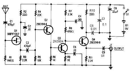
A simple active antenna can be designed using this electronic circuit diagram. This active antenna utilizes transistors and a few common electronic components. In the practice of short-wave frequency reception, a general rule is that a longer antenna will...
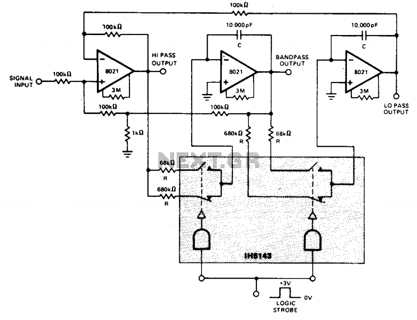
This constant gain, constant Q, variable frequency filter provides simultaneous low-pass, bandpass, and high-pass outputs. With the specified component values, the center frequency will be 235 Hz for high logic inputs and 23.5 Hz for low logic inputs. The...