
Super Cheap 1.5V Joule Thief circuit
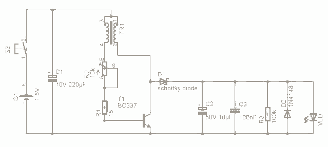
The Joule Thief is a simple yet effective boost converter circuit designed to extract energy from low-voltage power sources, such as depleted batteries. It operates on the principle of oscillation, utilizing a transistor to switch current through an inductor, which stores energy in its magnetic field. When the transistor turns off, this stored energy is released and stepped up to a higher voltage, allowing it to power devices that require more voltage than the source can provide.
The basic components of a Joule Thief circuit include a NPN transistor, a toroidal inductor or a ferrite core inductor, a resistor, and a diode. The transistor serves as the main switching element, while the inductor is crucial for energy storage and voltage boosting. The resistor is typically connected to the base of the transistor to limit the current and ensure proper operation. The diode is used to rectify the output voltage, allowing the energy to flow to the load.
When constructing a Joule Thief, the inductor is often wound with a specific number of turns, typically around 10 to 20 turns, depending on the desired output voltage and current. The choice of the transistor is also important; commonly used transistors include the 2N3904 or BC547. The circuit can operate efficiently with input voltages as low as 0.5V, making it ideal for scavenging energy from nearly depleted batteries.
The output voltage can vary depending on the load and the input voltage, but it can often exceed the input voltage by a factor of two or more, making it suitable for powering low-voltage LEDs or small electronic devices. The simplicity of the Joule Thief circuit, combined with its ability to utilize otherwise wasted energy, makes it a popular choice among hobbyists and engineers interested in low-power applications.For the past few days Ive been researching in this very interesting boost circuit called the joule thief (google it) and done allot of. The original schematic from google 🔗 External reference
Related Circuits
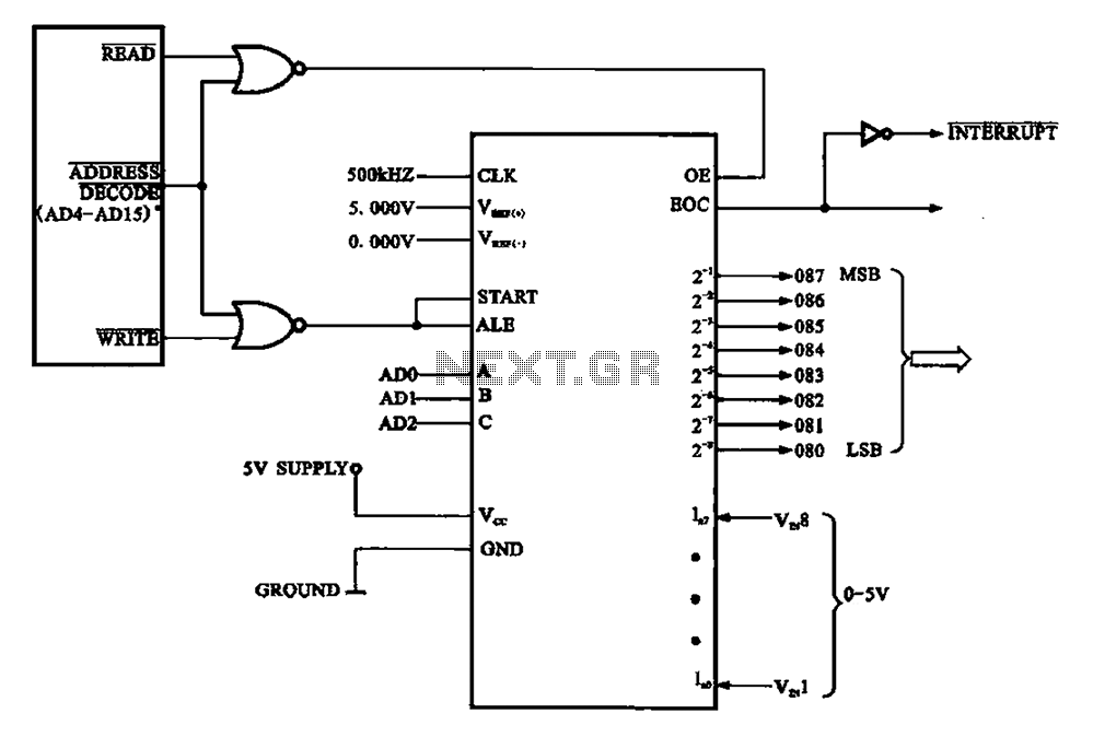
An A/D conversion circuit is designed to convert analog voltage into a digital signal encoding circuit. It utilizes ADC0808/ADC0809 circuit chips, which can convert analog signals into an 8-bit digital output signal. The A/D conversion circuit employs the ADC0808 or...
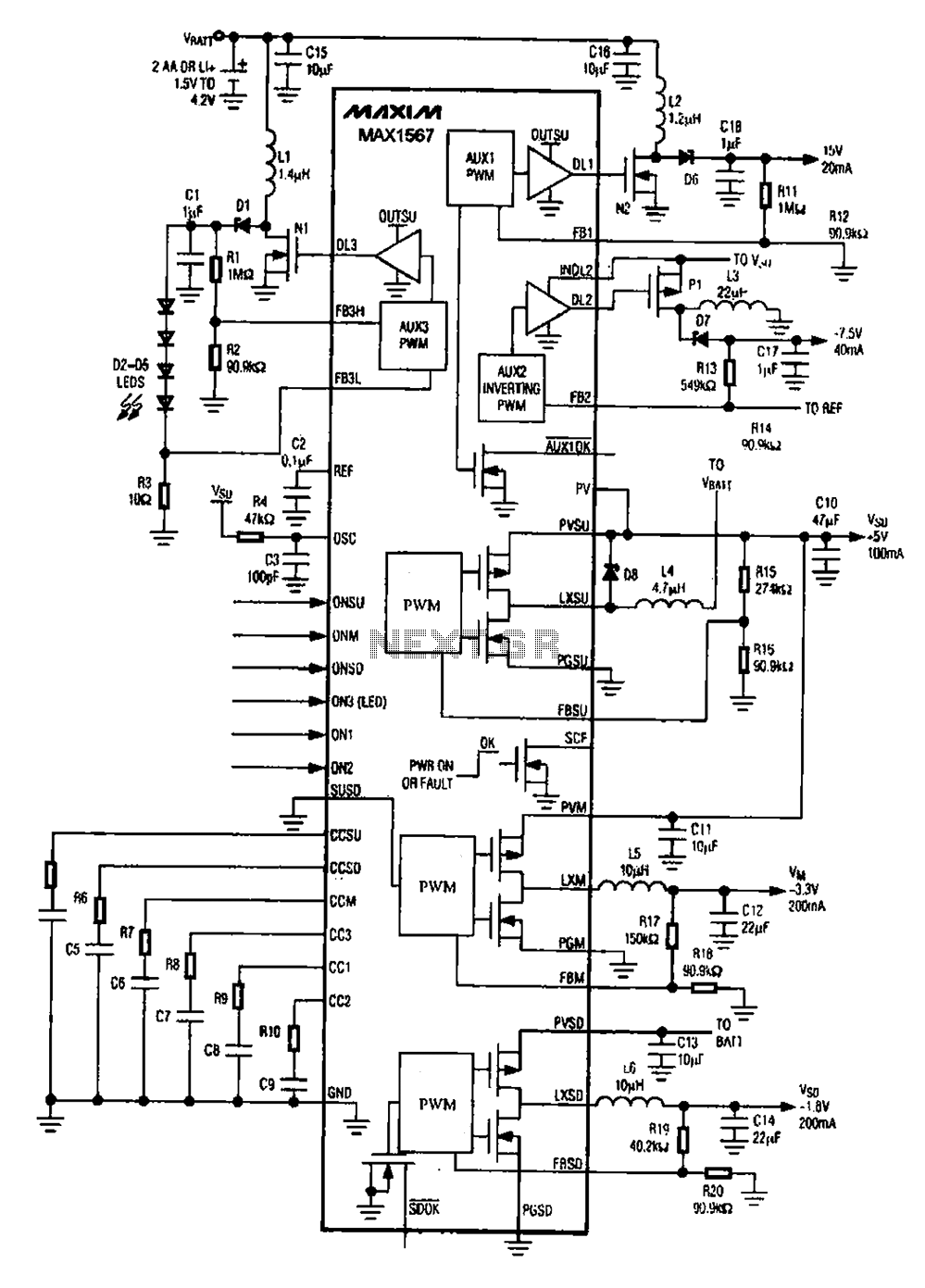
A brush 6-channel camera power supply circuit utilizing the MAX1566/1567. This circuit features a PWM generation system that is divided into six groups, with each group managing a separate channel. The circuit converts the DC voltage from the battery...
The power supply has been simplified. Power transformers and rectifiers have been omitted, and some components from the MOSFET voltage regulator circuits have been removed, including 1N5242 zener diodes between the source and gate and 10k resistors in series...
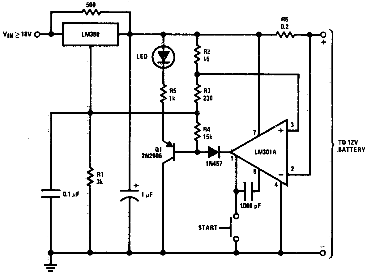
DC 12V Battery Charger Circuit Diagram. This circuit is a high-performance charger for gelled electrolyte lead-acid batteries. The DC 12V battery charger circuit is designed to efficiently charge gelled electrolyte lead-acid batteries, which are commonly used in various applications due...
A clock-and-data recovery (CDR) circuit is utilized to recover the clock from a transmitted data stream and re-time that data with the recovered clock. These circuits are generally positioned at the front-end of receiver chips to extract the clock...
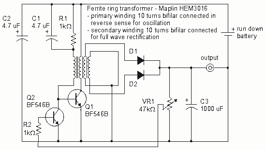
How to create a Joule Thief circuit to power a clock, including circuit details and tips for construction. The Joule Thief circuit is a simple and efficient boost converter that allows the extraction of usable voltage from low-voltage sources, such...