
Supply Voltage Indicator
This circuit operates as a voltage level indicator through the use of two LEDs and two transistors, providing both visual and intuitive feedback regarding the supply voltage. The first LED, LED1, serves as a primary indicator for voltages around the nominal 12 volts, illuminating steadily under normal conditions. The blinking behavior of LED1 below 11 volts serves as a warning, indicating a decline in supply voltage that may require attention. The gradual slowing of the blinking frequency offers an additional layer of information, allowing users to gauge the severity of the voltage drop.
LED2 complements the functionality by indicating higher voltage levels, activating at 13 volts and reaching full brightness at 14 volts. This dual-LED setup allows for a comprehensive view of the voltage status, with clear visual cues for both low and high voltage conditions. The adjustment of resistors R1 and R4 allows for customization of the voltage thresholds, making the circuit adaptable to various applications and requirements.
Transistor T1 plays a crucial role in generating oscillations when the input voltage is sufficiently high. The reverse bias condition in the emitter-collector path allows for a unique operational characteristic that can lead to oscillation. This behavior is particularly beneficial in providing a dynamic response to changing voltage levels, as the frequency of oscillation directly correlates with the input voltage. The use of the BC337-40 transistor is notable for its ability to initiate oscillations at lower voltages compared to other NPN transistors, which may require higher thresholds.
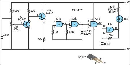
In summary, this circuit effectively combines visual indicators and adjustable components to create a reliable voltage monitoring solution. The design's simplicity and adaptability make it suitable for various applications, while the careful selection of components ensures functionality across a range of voltage conditions.This simple and slightly odd circuit can clearly show the level of the supply voltage (in a larger device): as long as the indicator has good 12 volts at its input, LED1 gives steady, uninterrupted (for the naked eye) yellow light. If the input voltage falls below 11 V, LED1 will start to blink and the blinking will just get slower and slower if t
he voltage drops further - giving very clear and intuitive representation of the supply`s status. The blinking will stop and LED1 will finally go out at a little below 9 volts. On the other hand, if the input voltage rises to 13 V, LED2 will start to glow, getting at almost full power at 14 V. The characteristic voltages can be adjusted primarily by adjusting the values of R1 and R4. The base-emitter diode of T2 basically just stands in for a zener diode. The emitter-collector path of T1 is inversely polarized and if the input voltage is high enough - T1 will cause oscillations and the frequency will be proportional to the input voltage.
The relaxation oscillator ceases cycling when the input voltage gets so low that it no longer can cause breakdown along the emitter-collector path. Not all small NPN transistors show this kind of behavior when inversely polarized in a similar manner, but many do.
BC337-40 can start oscillations at a relatively low voltage, other types generally require a volt or two more. If experimenting, be careful not to punch a hole through the device under test: they oscillate at 9-12 V or not at all.
🔗 External reference
Related Circuits
Under the loading condition of the resistance, the output voltage (Uo) variable range is from 30V to 36V, with a maximum output current (Imax) of 2A. When the input voltage (U2) changes from 15V to 21V, the voltage regulation...
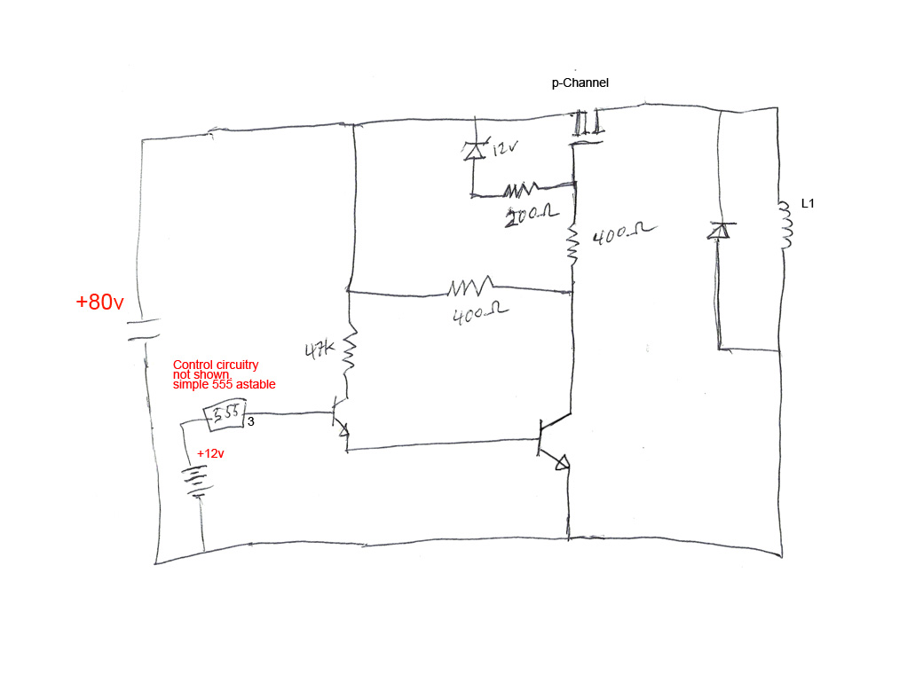
The circuit's premise involves powering an L1 coil with square pulses. A freewheeling diode is included to manage the back EMF field collapse, thereby protecting the circuitry. Previous experiments indicated that using an N-channel MOSFET on the high side...
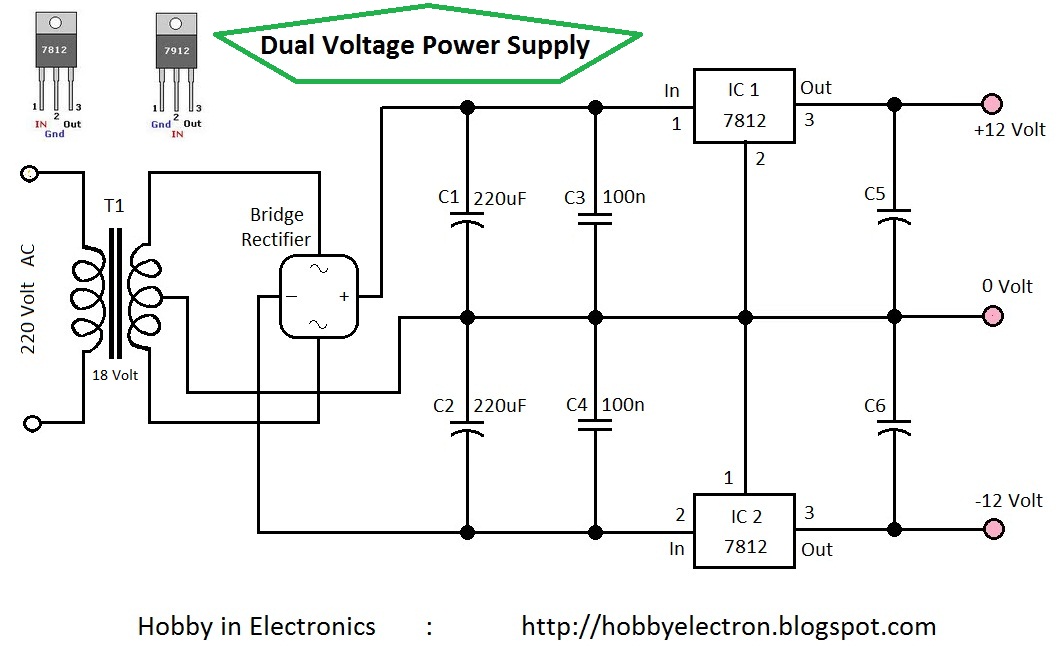
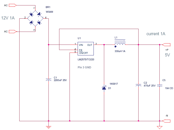
Circuit Home 7809 7812 7909 7912 Dual Voltage Hobby Electronics Hobby electronics projects RC filters REGULATOR transformer Dual Voltage Power Supply 12 Volt This is the simple circuit diagram of a Dual Voltage Power Supply. It is used for...
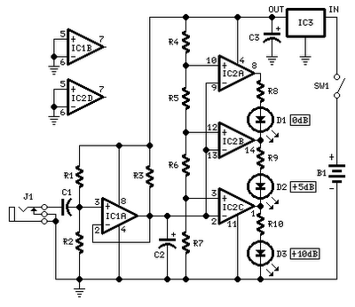
No setup is required: if correct values are used for resistors R3 to R7, LED D1 will illuminate at 0 dB input (0.775V RMS), LED D2 at +5 dB input (1.378V RMS), and LED D3 at +10 dB (2.451V...
This design integrates power-on and low-battery indications, capable of operating with any battery voltage up to 15V. It features a very low current drain of 2mA or less and costs less than $3.50 with new components. When the battery...
A power transistor with a voltage drop of 4 volts and a current of 3 amps may dissipate approximately 12 watts of heat, presenting a challenge in series regulators. In contrast, a saturated transistor or MOSFET with a voltage...