
Surfmaster PI Metal Detector Schematic Diagram

The circuit utilizes a TIP32C transistor as a switching element, which may exhibit overheating under certain conditions, indicating potential inefficiencies or excessive load. The IRF9640 MOSFET serves as a suitable alternative due to its higher efficiency and thermal performance, particularly in applications requiring rapid switching and low on-resistance.
In the circuit, R6 plays a critical role in controlling the timing and damping characteristics of the coil. The selection of this resistor is pivotal for optimizing the performance of the circuit. A standard 390-ohm resistor may suffice for many applications; however, variations in the load or operating conditions may necessitate adjustments to this value.
To facilitate precise tuning, employing a trim potentiometer in the range of 470 to 1k ohms allows for fine adjustments. This flexibility enables the user to empirically determine the most effective dumping resistor value. The optimal resistance can significantly influence the transient response of the system, enhancing stability and performance.
Additionally, careful attention should be paid to the thermal management of the components in the circuit. Adequate heat sinking or thermal dissipation methods may be required, especially when using the TIP32C, to prevent thermal runaway and ensure reliable operation. The transition to the IRF9640 MOSFET may alleviate some of these thermal concerns due to its enhanced heat dissipation capabilities.
Ultimately, the choice of components and their respective values should be guided by the specific application requirements, load characteristics, and desired performance metrics of the circuit.If TIP32C (Q2) gets excessively hot, use an IRF9640 MOSFET instead. Experiment with different values for R6 to find the optimal value (I use a 390 ohm resistor). Temporarily substitute R6 for a trim potentiometer (470 or 1k) to find the optimal dumping resistor for your coil. 🔗 External reference
Related Circuits
When both S1 and R2 are activated, current flows through each of the lamps connected in parallel to the rheostat. The current flow, and consequently the intensity of illumination, can be regulated by adjusting the effective voltage from the...
Here are some schematics and information that can be difficult to locate elsewhere. If there are schematics that should be included in this collection, please feel free to reach out. The intention is to expand this collection over time,...
The circuit employs an infrared (IR) phototransistor, designated as Q1, to sense the IR output signal from a remote control. The output from Q1 is then amplified by a PNP transistor, labeled Q2, which activates LED1. This illumination indicates...
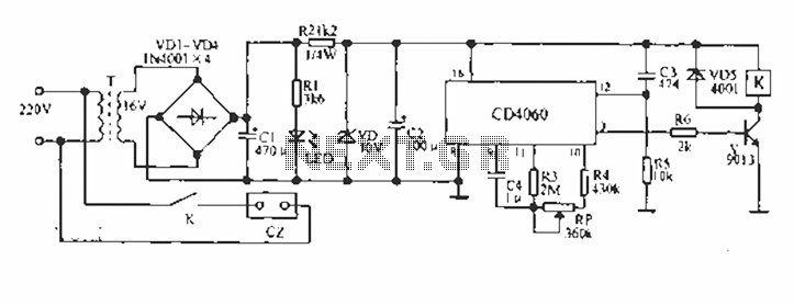
A CD4060 production time controller circuit is illustrated below. It is connected in such a way that R5 and C3 form a differential circuit to create a delay time from the start. Under the influence of the oscillating signal,...
The device is designed to accelerate the defrosting process of fish, meat, and other foods by utilizing audio vibrations. This method allows for defrosting in warm water, significantly reducing the time required compared to conventional methods, while preserving the...
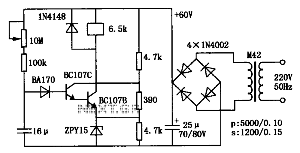
The circuit is a relay delay pull transistor configuration. Initially, when powered, the 16 µF capacitor has a voltage of zero, resulting in both transistors being off, and the relay remains inactive. As the 16 µF capacitor charges over...