
swr pwr

The designed circuit board for the Stockton-type SWR/PWR meter emphasizes compactness and ease of assembly, making it suitable for QRP (low power) applications. The use of a single-sided copper-clad board facilitates straightforward fabrication, allowing hobbyists to replicate the design with minimal equipment. The method of using a Dremel tool to cut traces is particularly advantageous for those without access to professional PCB etching facilities.
The choice of toroidal transformers (T1 and T2) is crucial in maintaining the performance of the SWR/PWR meter. The FT37-61 cores, while smaller than the typical FT50-61, are sufficient for QRP levels, demonstrating that size does not always compromise functionality. The design's adaptability, particularly the potential substitution of coax with insulated wire, reflects a practical approach to circuit design, allowing for experimentation while considering component availability.
The circuit's simplicity is further enhanced by the minimal parts count, which not only reduces assembly time but also makes it easier for builders to source components. The dual-resistor configuration for achieving 50-ohm impedance is a common practice in RF circuits, ensuring proper matching and efficient power transfer.
Calibration procedures are user-friendly, allowing for quick adjustments to accommodate various operating conditions. The option to use two meters for simultaneous monitoring of forward and reflected power can be particularly useful for those looking to optimize their antenna systems. Overall, the described SWR/PWR meter circuit is an excellent example of practical electronics design, merging compactness with functionality, making it an ideal project for amateur radio enthusiasts.After building my Z-match tuner, I wanted to design a circuit board for a Stockton type swr/pwr meter that I could reproduce easily and see how small I could make it. The result is in the above picture. It is a board that measures a scant 1" x 1. 5" and is made from common single sided copper clad board. I drew the lines on the board with a pencil, and then used a Dremel tool and an abrasive wheel to cut the traces in the copper that isolates the individual pads that the components solder to. The circuit is a variant of the Stockton type of bridge used in many commercial swr/pwr meters and kits these days.
The design calls for a short piece of coax going through each toroidal sensor with the shield grounded at one end only to eliminate harmonic currents, but I am going to experiment with just an ordinary piece of insulated wire due to the fact that my circuit will be used at QRP levels only. Will let you all know how this works out once I get it all tested. Figure 1 above shows the PC board dimensions and pad locations. You could etch this board, but it is so simple, it is real easy to just sketch the lines on the board using a pencil and ruler and then use the Dremel tool to cut the traces.
Figure 2 above shows the board with the parts location marked. As you can see, the design is straight forward and parts count is minimal. The circuit and board is so small that it will fit inside many QRP rigs. The only thing wrong with that is the fact that it may be hard to find a panel meter small enought to fit the rig. The circuit will fit easily inside an Altoids tin, and there are many old CB radios out there that you can rob the meter out of that is small enough to fit the Altoids tin also.
You can also fit this circuit inside that QRP antenna tuner you have been planning on building ! It`s the same circuit that I built in my Z-match tuner, except I used a Radio Shack general purpose perf board for that one. And finally, here is the schematic for the swr/pwr meter circuit. T1 & T2 in most Stockton type bridges call for an FT50-61 core, but I used the smaller FT37-61 cores to save space, and have had no problems with them when using QRP power levels.
T1 & T2 each have 12 turns of #24 enamel wire, and the secondary is usually a short section of coax with the shield grounded at one end only to form what is known as a Faraday shield that helps eliminate harmonic currents that may cause the meter readings to be inaccurate. But like I said, since I am building this one to be used at QRP levels only, I decided to experiment with just an ordinary piece of insulated wire in place of the coax just to see how it works.
If it works ok, it will make the reproduction of this circuit much easier in the future because the coax seems to be the hardest part of the circuit to deal with. At least is is for me anyway ! The 50 ohm resistors in the circuit are made by connecting two 100 ohm 1/4 watt carbon resistors in parallel, so you will need 4 100 ohm resistors to make 2 50 ohm resistors unless you can find some 1/4 watt 50 ohm resistors.
I think you can get 51 ohm resistors, and if you get the 5% tolerance resistors, that should be close enough and since you will only need 2 of them, it saves even more space on the circuit board. The schematic only shows one meter with a switch to select either forward or reflected power. You can eliminate the switch and use 2 identical meters if you have them and monitor both forward and reflected power at the same time.
Calibrating the meters is done by adjusting the variable resistors on the board. I usually just set mine to read full scale for the power level that I am using on the forward side, and set it to just read zero on the reflected side with full power applied and a 50 ohm dummy load connected to the output and use them for a relative reading instrument. I`m really not worried about accurate measurement of forward power, and on the reflect 🔗 External reference
Related Circuits
This is an unconventional circuit for an ultra-low distortion power amplifier. The circuit, noted to be from January 1977, is not modern but still sufficiently unique to warrant interest. It was designed and sold as a card by a...
A schematic diagram for a broadband QRP SWR metering circuit intended for use in a QRP antenna tuner. The circuit allows the user to press a momentary DPDT switch to observe an LED indicator while adjusting the capacitors of...
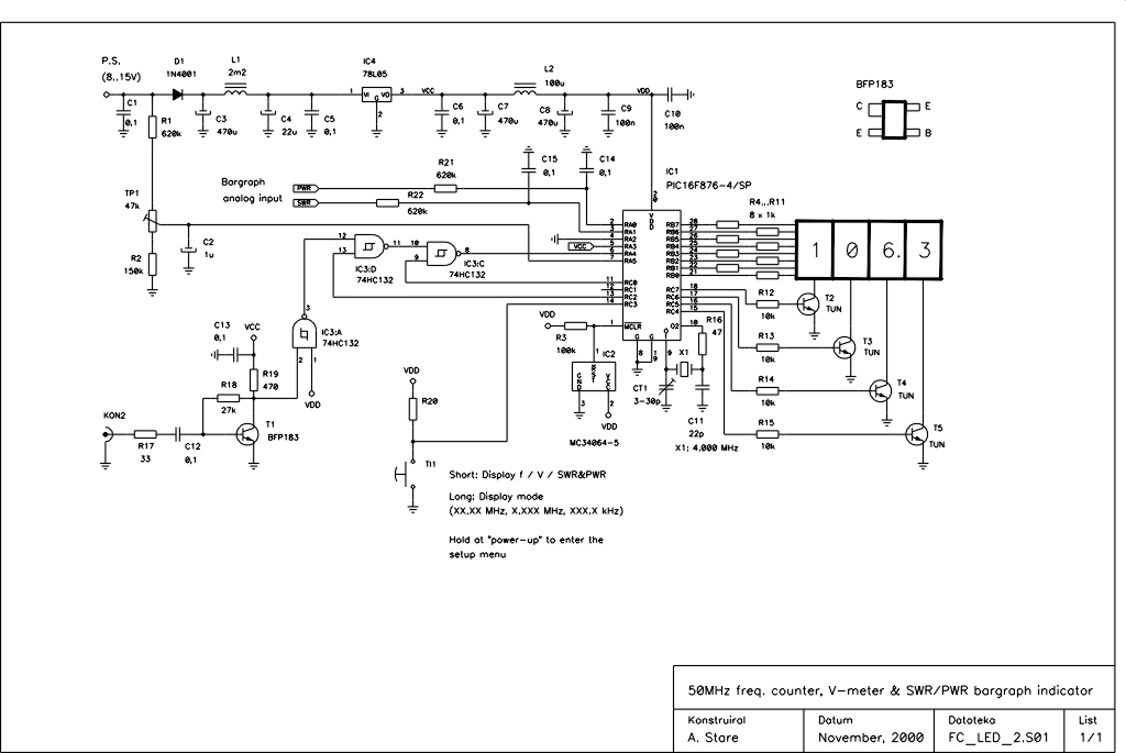
This device is an upgraded version of the PIC16C71 4-digit LED frequency counter and voltmeter. It eliminates several hard-to-find components from the previous model, which have been out of production for some time. The older PIC16C71 has been replaced...
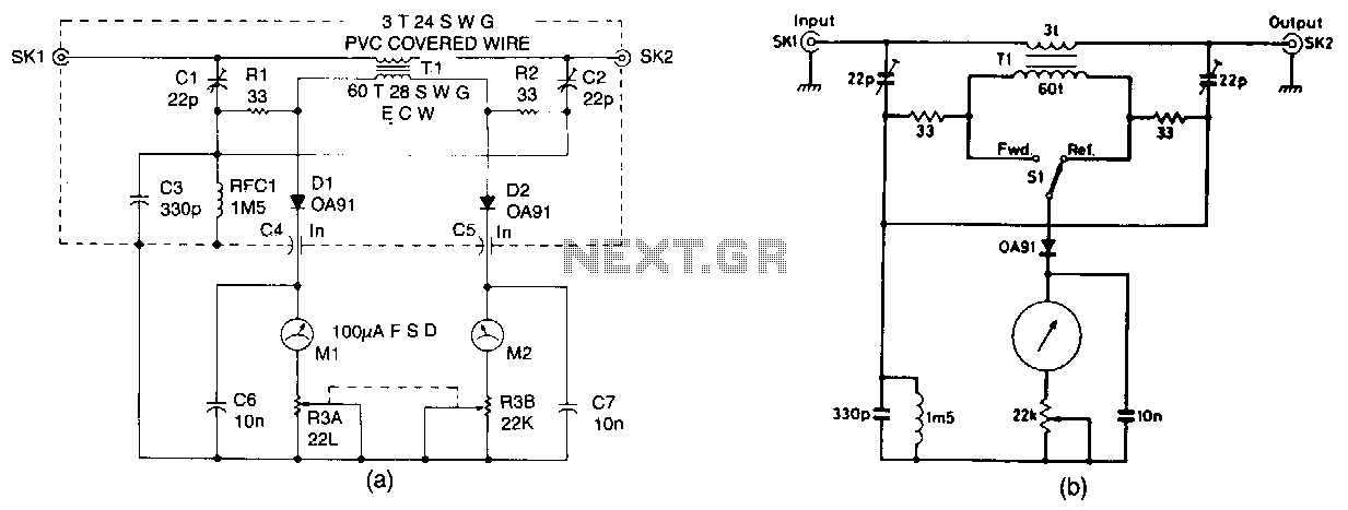
The design presented is a straightforward unit intended for QRP (low-power) operation across all authorized frequencies up to 30 MHz. It utilizes a toroidal transformer (T1). The secondary winding of T1 captures a small portion of RF power, both...
This document outlines a simple SWR meter designed for long and medium wave bands (137 kHz and 500 kHz). The design is not novel and resembles common short wave meters, but it has been specifically created to operate at...
This document describes a simple 2.4 GHz SWR meter that utilizes surplus microwave hardware. The main component is a MECA -20/-20 dB Directional Coupler, which operates within a frequency range of approximately 700 MHz to 2.5 GHz. This directional...