
Automatic toilet flushing circuit

The automatic toilet flusher circuit operates on a straightforward yet effective principle, integrating various electronic components to ensure reliable performance. The power circuit is crucial, consisting of a step-down capacitor (C1) that reduces the input voltage, a rectifier diode (VD1) that converts AC to DC, and a Zener diode that regulates the output voltage. The filtering capacitor (C2) smooths the voltage supply, ensuring stable operation of the circuit.
The monostable circuit is the heart of the flushing mechanism. It utilizes an integrated circuit (IC) that responds to voltage levels at its input pins. When the toilet lid is opened, the switch S is activated, allowing the power supply to charge the system. The IC monitors the voltage levels, and when the voltage at the trigger pin exceeds a third of the supply voltage (Vcc/3), it changes the output state, allowing the relay K to remain inactive while the capacitor charges.
Upon closing the toilet lid, the power is cut off, but the isolation diode (VD2) allows the capacitor to discharge through the resistor (Rz), triggering the IC. This transition activates the relay K, which connects the power supply to the solenoid valve (Y), initiating the flushing process. The system is designed to ensure that the flush occurs only once per use, thanks to the thyristor (VTH) that discharges and prevents multiple activations.
The timing and control of the flush are managed by the charging of capacitor C3, which, when charged to a specific voltage, causes the IC output to revert, deactivating the relay and cutting power to the circuit. This design allows for efficient energy management and ensures that the automatic toilet flusher operates smoothly and reliably, providing a user-friendly experience while conserving power. Automatic toilet flusher is restructuring in the sitting so that the basis of the ordinary, the automatic flush after use once, simple and reliable. When not in power source co mpletely disconnected, with energy-saving, easy to use, long life chip advantage. (1) circuit automatic flush toilet circuit from the power circuit, monostable solenoid valve and control circuit, as shown 1-47 Fig. Power circuit consists of step-down capacitor C1, rectifier diode VD1, Zener diode and capacitor C2 vs other components.
(2) the work process open toilet lid, the switch S is turned on, AC 220V voltage by cI Buck, VD1 rectifier, vs regulator and G after filtering, to provide the power supply circuit.. . : Monostable circuit from when base integrated circuit lc and relevant peripheral components. foot trigger terminal 1C initial voltage by Rz, R3 partial pressure is higher than after Vcc/3, lC the pin output low, the single-shot in the steady state, the relay K is not action, large-capacity capacitor is charged 0 full power.
After use, when the toilet lid cover, switch S off, the circuit power outages, due to the isolation of VD2 charge cz Rz on the quickly let go and Po. lC of pin goes low is triggered. In this case the bulk capacitor G is the IC supply through diode VD3, one-shot circuit is triggered transient backward people, ICs pin goes high, the relay K leisure together.
After K closed self-locking, so that the circuit to restore power supply, K closed connected to electric solenoid valve Y, start flushing. Meanwhile, the power supply via a resistor horse C3 charging, when charging so C3 rises to the potential of pin IC 2Vcc/3 resistance, temporary end state, lC of foot turned back low, the relay K release, K OFF, the The entire circuit power, flush ends.
Used in the circuit of the thyristor VTH G discharge, ensure that only flush once. When the IC foot just flip from low to high, VTH is triggered conduction, the G discharge voltage drops 2 ~ 3V. If set G discharge circuit, the lC after the transient, the relay K release put, K suddenly disconnected the circuit energized, ICs feet and jump into a low, G by VD3 supplies power to lC, single steady circuit again and again by the trigger, and pull the relay K, and so forth cycle.
Related Circuits
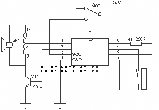
The alarm circuit operates as follows: When the power switch SW1 is turned on, the alarm system becomes active. If a magnet is brought close to the spring, the magnetic field attracts the spring, causing the dynamic and static...
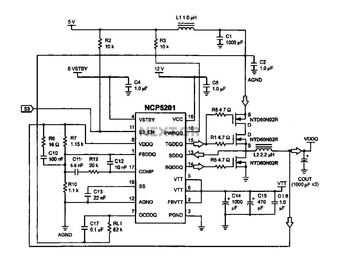
Computer memory power supply circuit (NCP5201). This circuit illustrates a typical power supply configuration for computer memory, utilizing the NCP5201 power management chip. It features a dual-output design. The NCP5201 is a highly integrated power management solution designed specifically for...
There are monitors that feature only three BNC inputs and utilize composite synchronization (sync on green). This circuit has been specifically designed for such monitors. The design maintains simplicity while delivering reasonable performance. The operational principle is straightforward. The...
This is a transistor inverter circuit diagram rated for 100 watts, designed as an easy-to-build circuit. It utilizes only transistors and does not incorporate any integrated circuits. The circuit converts a 12V battery input to a 220V, 50Hz square...
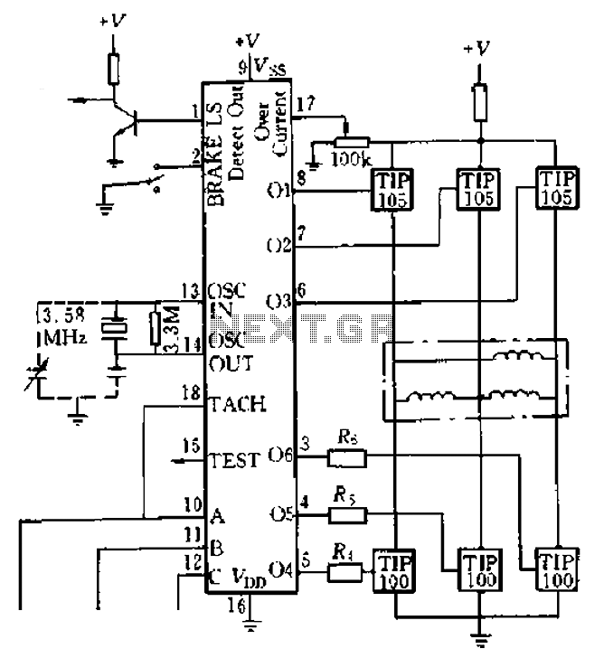
Four application examples are presented in the figure, focusing on a three-phase brushless DC motor used in Winchester disk drives with an operating speed of 3600 RPM. Although the original design specifies an operating speed of 3600 RPM, alternative...
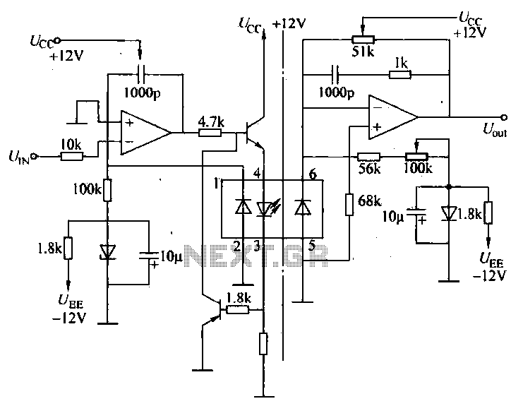
A universal optocoupler is utilized in electrocardiographs, as illustrated in Figure 5-29. Pin connections must be made carefully: the positive terminal should be connected to pin O, while the negative terminal should connect to the other pin. The control...