
Tan Timer
The tanning timer circuit incorporates a rotary switch that allows users to select from six distinct photo-type settings. Each setting corresponds to varying skin sensitivities to UV radiation, enabling users to tailor their tanning duration according to their skin type. The rotary switch is connected to a microcontroller that interprets the selected position and adjusts the timer accordingly.
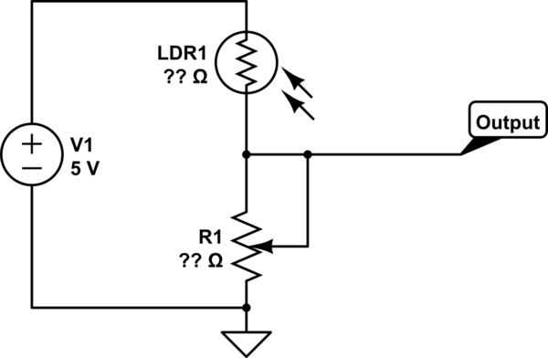
A photoresistor (LDR) is integrated into the circuit to monitor ambient light levels. This component is crucial as it modifies the timer's preset duration based on the intensity of sunlight detected. The photoresistor's resistance decreases with increasing light intensity, which is measured by the microcontroller. The microcontroller uses this data to adjust the timing, ensuring that users do not exceed safe exposure limits even on particularly sunny days.
The circuit may also include a visual or audible alarm system that alerts users when the timer has expired, promoting safety and preventing overexposure to UV radiation. Power management features, such as a low-power mode or battery backup, can be integrated to enhance usability and reliability.
Overall, this tanning timer circuit combines user-friendly features with safety mechanisms, making it an essential tool for individuals seeking to enjoy the sun responsibly.This timer was designed for people wanting to get tanned but at the same time wishing to avoid an excessive exposure to sunlight. A Rotary Switch sets the timer according to six classified Photo-types (see table). A Photo resistor extends the preset time value according to sunlight brightness (see table). 🔗 External reference
Related Circuits
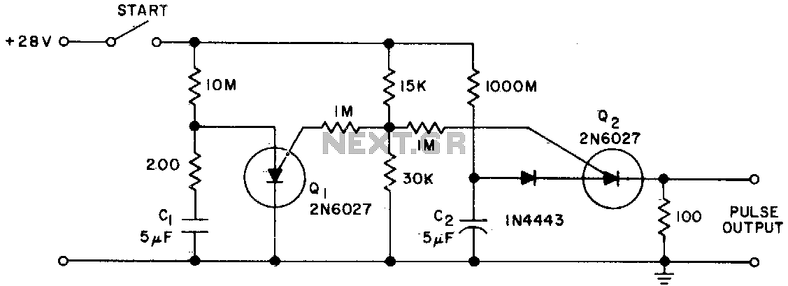
The Programmable Unijunction Transistor (PUT) serves as both a timing element and a sampling oscillator. A low leakage film capacitor is required for capacitor C2 because of the minimal current supplied to it. The Programmable Unijunction Transistor (PUT) is a...
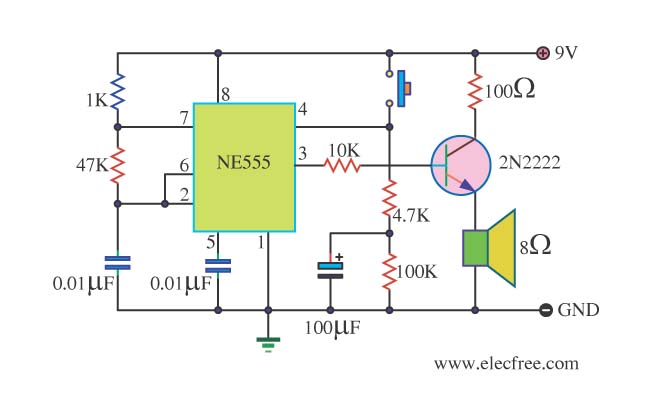
This is a danger beep circuit. It uses a 555 integrated circuit configured as a stable multivibrator that provides a duty cycle of 5% to drive a loudspeaker. The danger beep circuit utilizes the 555 timer IC, a versatile and...
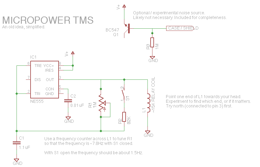
Let's face it, not every day is the greatest. Sometimes, one may not feel like doing much of anything. Wouldn't it be nice if there was a way to change brain waves at the push of a button? Transcranial...
This part of the circuit is isolated from any other component, except for the 5V and ground connections. It includes LEDs and a shift register, which may not interact significantly. The LDR (Light Dependent Resistor) is utilized solely as...
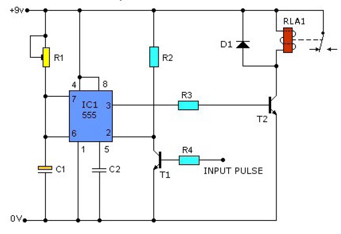
This causes T1 to conduct, pulling pin 2 of IC1 low. IC1 then enters a timing cycle, the duration of which is set by R1 and C1, resulting in pin 3 of IC1 going high. This action causes T2...
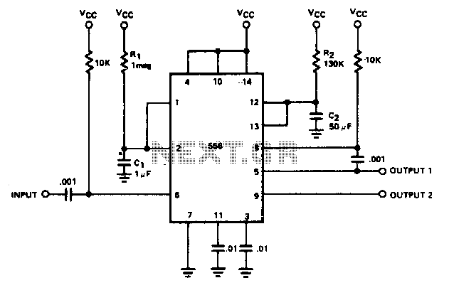
By utilizing both halves of a dual timer, sequential timing can be achieved. The output of the first half is connected to the input of the second half through a 0.1 µF coupling capacitor. The delay time ti is...