
Telephone DTMF decoder Display
The circuit operates by utilizing the Dual-Tone Multi-Frequency (DTMF) signaling method, which is standard in telephone systems for dialing. The core of the circuit is the DTMF decoder (CM8870P1, IC1), which interprets the DTMF tones generated when a number is dialed. It converts these tones into a Binary-Coded Decimal (BCD) representation, allowing the circuit to process the number.
The BCD outputs from IC1 are then directed to a series of latches (IC5A and IC5B, part of CD4508) that store the dialed numbers. The first dialed number is stored in IC5A, while subsequent numbers are stored in IC5B and so forth, enabling the storage of up to ten digits. Special attention is given to the representation of the digit '0', which is decoded as '1010' in binary. To ensure compatibility with the seven-segment display (IC10), a logic circuit is implemented to convert the binary output of '1010' to '0000', allowing for proper display functionality.
The latching mechanism is controlled by a decade counter (IC2, 4017) that is clocked by the data valid output from IC1. This setup ensures that each time a new number is dialed, the previous data in the latches is cleared, and new data is stored sequentially. The outputs from IC2 are connected to the store and clear inputs of the latches, ensuring that only one latch is active at a time for data storage.
The displays are driven by a single seven-segment decoder (IC10), which minimizes the overall size and power consumption of the circuit. The decoder activates the appropriate display based on the data stored in the corresponding latch. The latches are controlled by additional logic circuits (IC3, IC12, IC13), which manage the enable signals for the displays. An astable multivibrator (IC4, 555) serves as the clock source for IC3, facilitating the timing necessary for display updates.
For user interaction, the circuit is designed to connect to telephone lines via a DPDT switch, allowing manual control over the circuit's operation. Alternatively, automatic switching can be achieved through a circuit that detects the off-hook condition of the telephone. The design also allows for flexibility in display configuration, enabling the user to limit the number of displayed digits by connecting the reset pin of IC2 accordingly.
The construction of the circuit can be accomplished on a veroboard, and it is recommended to house the completed assembly in a suitable enclosure for protection and usability. The common-cathode configuration of the displays allows for straightforward integration into the circuit, and the option to use different colored displays can enhance visual distinction for various components of the dialed number. Overall, this circuit provides a practical solution for displaying dialed numbers in a telephone system using DTMF technology.The given circuit, when connected in parallel to a telephone, dis- plays the number dialled from the telephone set using the DTMF mode. This circuit can also show the number dialled from the phone of the called party. This is particularly helpful for receiving any number over the phone lines. The DTMF signal generated by the phone on dialling a number is decoded by DTMF decoder CM8870P1 (IC1), which converts the received DTMF signal into its equivalent BCD number that corresponds to the dialled number.
This binary number is stored sequentially in 10 latches each time a number is dialled from the phone. The first number is stored in IC5A (1/2 of CD4508) while the second number is stored in IC5B and so on.
The binary output from IC1 for digit 0 as decoded by IC1 is 10102 (=1010), and this cannot be displayed by the seven-segment decoder, IC10. Therefore the binary output of IC1 is passed through a logic-circuit which converts an input of 10102 into 00002 without affecting the inputs 1 through 9.
This is accomplished by gates N13 through N15 (IC11) and N1 (IC12). The storing of numbers in respective latches is done by IC2 (4017). The data valid output from pin 15 of IC1 is used to clock IC2. The ten outputs of IC2 are sequentially connected to the store and clear inputs of all the latches, except the last one, where the clear input is tied to ground. When an output pin of IC2 is high, the corresponding latch is cleared of previous data and kept ready for storing new data.
Then, on clocking IC2, the same pin becomes low and the data present at the inputs of that latch at that instant gets stored and the next latch is cleared and kept ready. The similar input and output pins of all latches are connected together to form two separate input and output buses.
There is only one 7-segment decoder/driver IC10 for all the ten displays. This not only reduces size and cost but reduces power requirement too. The output from a latch is available only when its disable pins (3 and 15) are brought low. This is done by IC3, IC12 and IC13. IC3 is clocked by an astable multivibrator IC4 (555). IC3 also drives the displays by switching corresponding transistors. When a latch is enabled, its corresponding display is turned on and the content of that latch, after decoding by IC10, gets displayed in the corresponding display. For instance, contents of IC5A are displayed on display DIS1, that of IC5B on DIS2 and so on. The system should be connected to the telephone lines via a DPDT switch (not shown) for manual switching, otherwise any circuit capable of sensing handset s off-hook condition and thereby switching relays, etc.
can be used for automatic switching. The power-supply switch can also be replaced then. Though this circuit is capable of showing a maximum of ten digits, one can reduce the display digits as required. For doing this, connect the reset pin of IC2, say, for a 7-digit display, with S6 output at pin 5. The present circuit can be built on a veroboard and housed in a suitable box. The displays are common-cathode type. To make the system compact, small, 7-segment displays can be used but with some extra cost. Also, different colour displays can be used for the first three or four digits to separate the exchange code/STD code, etc.
The circuit can be suitably adopted for calling-line display. 🔗 External reference
Related Circuits
A universal digital gear display that can be installed on any motorbike. This is a low-cost solution based on simple TTL digital technology without software programming. The universal digital gear display is designed for easy installation on a variety of...
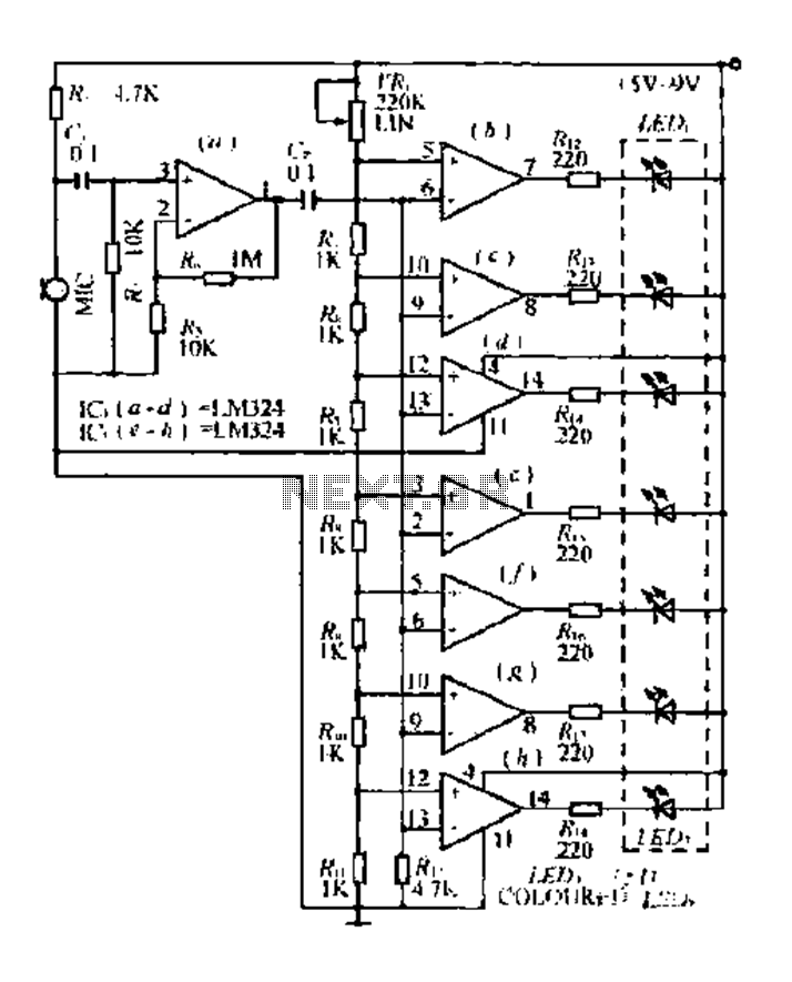
The condenser microphone pickup signal is processed by an integrated circuit (IC) where it is amplified and compared using a comparator circuit. The outputs from the comparators, designated as IC1, IC2, and IC3, provide voltage comparisons based on different...
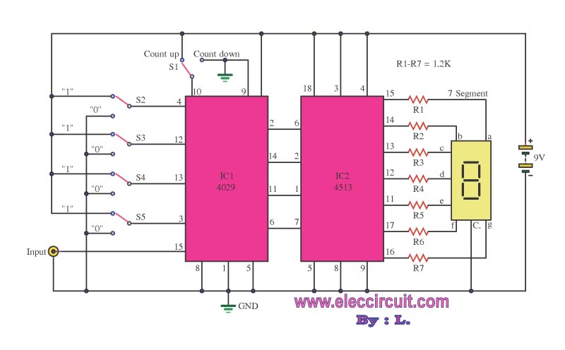
This is a simple digital counter circuit utilizing the IC 4029 to process binary data, which is then sent to the IC 4513, a driver IC for a 7-segment display to show the output. The digital counter circuit is designed...
Small telephone bug. It listens to the telephone line on an FM receiver. It is self-powered and has a small part count. Circuit diagram, schematics, electronics project. The small telephone bug is a compact and efficient device designed to intercept...
The following text describes construction, testing and use of an electronic telephone line simulator of my own design. This self-build project can simulate a telephone call / connection between any two local telephone devices. This for a fraction of...
The telephone ring generator illustrated below produces the necessary high voltage using a simple switching mode power supply (SMPS) that incorporates a CMOS Schmitt Trigger square wave oscillator, a 10 mH inductor, a high voltage switching transistor (such as...