
Telephone Call Recorder
The described call recording circuit is relatively simple but requires careful assembly and understanding of the components involved. The circuit primarily consists of a few resistors, capacitors, diodes, and a stereo jack, making it cost-effective and accessible for various applications. The use of the RJ11 connector ensures compatibility with standard landline phones, while the stereo jack facilitates easy connection to recording devices.
The circuit operates by tapping into the phone line's voltage, allowing the conversion of the incoming call signal into a format suitable for recording. The diodes play a crucial role in rectifying the AC voltage generated by the incoming call, ensuring that only the necessary DC voltage is passed to the recording device. The resistors are strategically placed to manage the voltage levels, protecting sensitive components and ensuring optimal audio quality.
When assembling the circuit, attention should be paid to the placement of components on the PCB to minimize interference and maintain signal integrity. The choice of a shielded cable for connections helps to further reduce noise and ensure clearer recordings. Additionally, the ability to adjust the volume output via resistor R2 provides flexibility in recording levels, accommodating various recording environments and user preferences.
In summary, this call recording circuit is a practical solution for capturing phone conversations, applicable in diverse settings from professional environments to personal use. Proper assembly, component selection, and attention to detail will yield a reliable device capable of high-quality audio recordings.Today phone has become an integral part of our lives. It is the most widely used communication tool in the world. Owing to its immense popularity & widespread use, there arises a necessity for call recording devices, which find application in call cent-res, stock broking firms, police, offices, homes, etc. Here they are describing a call recorder that makes use of only a few parts. But in order to understand its working, must first have the basic knowledge of standard phone wiring as well as a stereo plug. In India, land-line rings primarily use RJ11 wiring, which has wireless-tip & ring. While tip is the positive wire, ring is the negative. & together they complete the phone circuit. In a phone line, voltage between tip & ring is around 48V DC when handset is on the cradle(idle line).
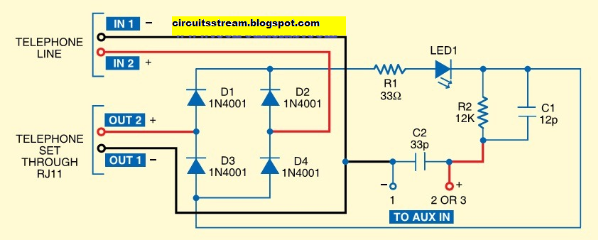
In order to ring the phone for an incoming call, a 20Hz AC current of around 90V is superimposed over the DC voltage already present in the idle line. The negative wire from the phone line goes to IN1, while the positive wire goes to IN2. Further, the negative wire from OUT1 & the positive wire from OUT2 are connected to the phone. All the resistors used are 0. 25W carbon film resistors & all the capacitors used are rated for 250V. The negative terminal of To AUX IN is connected to pin one of the stereo jack while the positive terminal is connected to pins two and three of the stereo jack.
This stereo jack, in turn, is connected to the AUX IN of any recording tool, such as computer, audio cas-setts player, CD player, DVD player, etc. Here they shall be connecting it to a computer. When a call comes in, around 90V AC current at 20Hz is superimposed over the DC voltage already present in the idle line.
This current is converted in to DC by the diodes & fed to resistor R1, which reduces its magnitude & feeds it to LED1. The current is further reduced in magnitude by the resistor R2 & fed to the right & left channels of the stereo jack, which are connected to the AUX IN port of a computer.
Audio recording application, can be used to record the call. When a call comes in, needs to launch the audio recording program and start recording. For phone recording, basically connect the stereo jack to the AUX IN port of the PC. Install the Audacity audio recorder. Run the executable Audacity file. By & sizable window, you will discover a drop-down box in the top right corner. From this box, select the AUX option. Now you are prepared to record any call. As soon as a call comes in, press the record button present in the Audacity main window & then pick up the phone receiver & answer the call. Press the cease button one time the call ends. Now go to the file menu & select the Export as WAVE option & save the file in a desired location. You may change the worth of resistor R2 in case you require to change the output volume. You can use a variable resistor in series with R2 to vary the volume of the output. The recorded audio clip can be edited using different options in the Audacity application. You can assemble the circuit on a general-purpose PCB & enclose it in a small cabinet. Use an RJ11 connector & stereo jack for connecting the phone set & computer (for call recording). Phone cords can be used to connect to the phone line & the circuit. Use of a shielded cable is recommended to reduce disturbances in the recording. These may even be reduced by increasing the worth of R2 to about 15 kilo-ohms. 🔗 External reference
Related Circuits
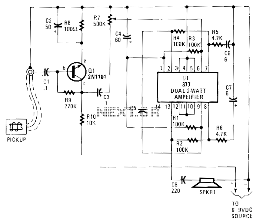
Audio from the telephone is inductively coupled to the base of Q1, which functions as a preamplifier. This preamplifier provides a gain of approximately 75 dB, boosting the input signal from around 4 mV to about 300 mV peak-to-peak....
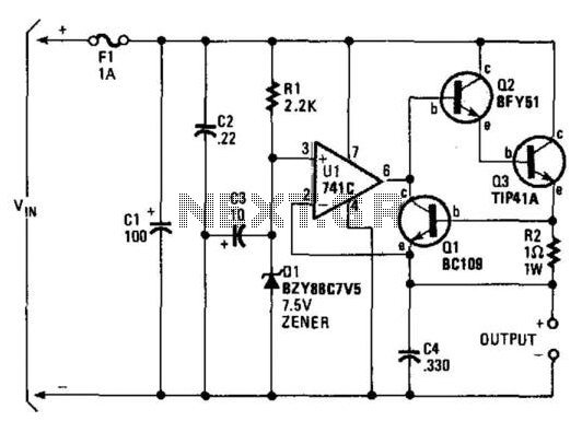
A regulator enables the powering of a 7.5-V cassette recorder or other devices from a 12-V DC automotive system. The circuit can provide approximately 600 mA of current. Q3 requires a heatsink due to its potential to dissipate up...
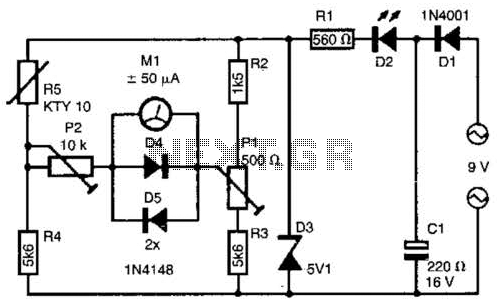
The telephone line tester comprises a meter used to measure line voltage in both the on-hook and off-hook states, three resistors (including one variable resistor), a pushbutton switch, and a modular telephone connector. When the circuit is connected to...
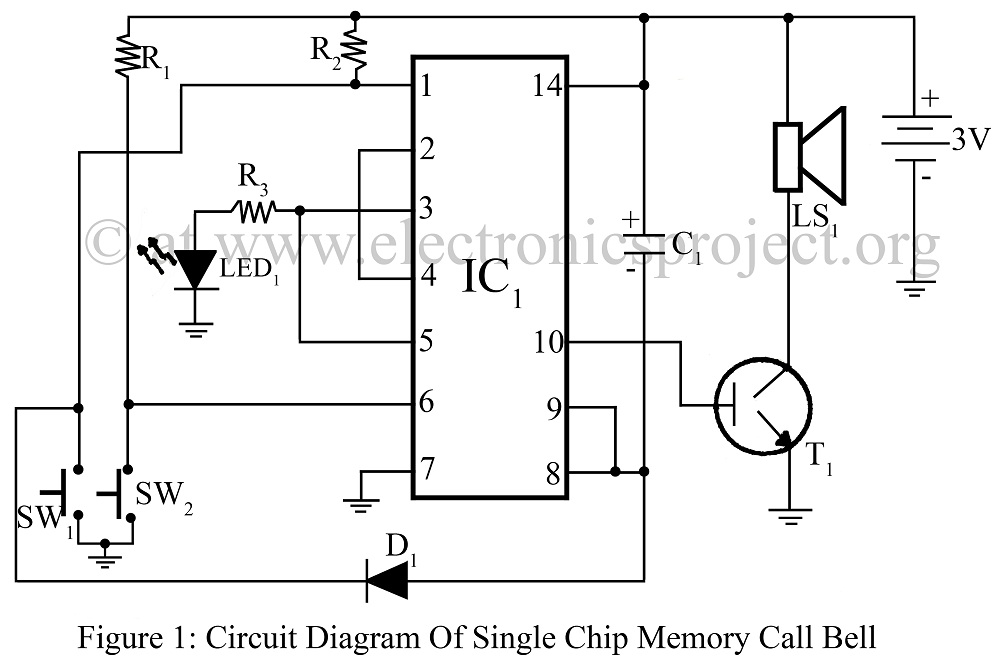
A single-chip memory call bell circuit utilizing a quad 2-input NAND gate (CD4011) that activates when a guest arrives in the absence of the homeowner. This circuit diagram includes various doorbell project configurations. The single-chip memory call bell circuit is...
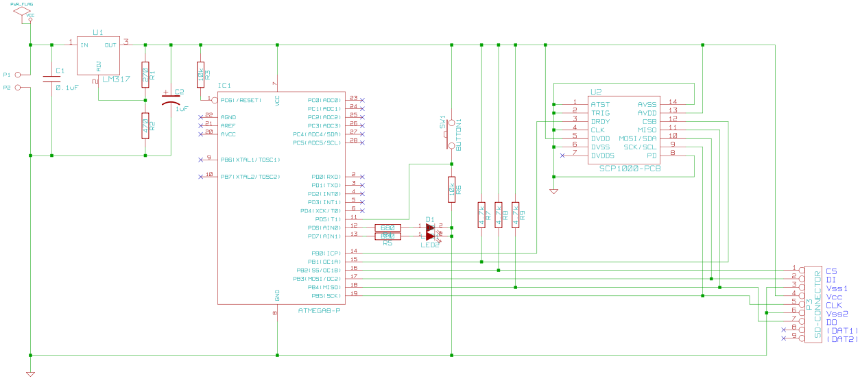
This circuit is designed to record the altitude of a remote-controlled (R/C) plane. The recorded data is stored on an SD card. It utilizes an ATmega8 microcontroller and a SCP1000 chip to measure temperature and, more importantly, atmospheric pressure....
The objective of this digital electronics project is to record messages using a dedicated voice recorder integrated circuit. Recordings are stored in non-volatile memory cells, ensuring that messages remain saved even when power is removed from the device. The...