
Telephone ringer piezoelectric
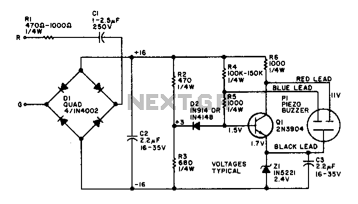
The electronic bell circuit is designed to function autonomously, utilizing a piezo buzzer as the sound-producing element. The circuit architecture is simplified, relying on passive components such as resistors and capacitors, with specific emphasis on the values of C2, R2, and R3, which are critical for optimal performance. The omission of resistor R1 is a design choice that directly influences the sound output level, allowing for a louder ringing tone, which may be desirable in certain applications.
The piezo buzzer, a key component in this circuit, is versatile and can be sourced from various suppliers, leading to potential variations in specifications. The connection scheme for the buzzer is straightforward: the red lead is to be connected to the collector of the transistor Q1, while the black lead connects to the emitter. This configuration is essential for the proper functioning of the circuit, as it allows the transistor to control the piezo buzzer effectively.
In cases where the piezo buzzer includes a third lead, typically colored blue, this lead is connected to the base of transistor Q1. This additional connection can enhance the control over the buzzer's operation, providing more refined modulation of the sound output. The overall design of the electronic bell circuit is efficient and user-friendly, making it suitable for various applications where a simple, battery-free sound signaling device is required.The electronic bell needs no power supply. Most of the resistors are not critical, although C2, R2, and R3 work best at the values given. Leaving out Rl will make the unit ring louder. The piezo buzzer may vary from store to store. If it has two leads, connect the red lead to the collector and the black lead to the emitter of Ql If a third (blue) lead is present, connect it to the base of Ql. 🔗 External reference
Related Circuits
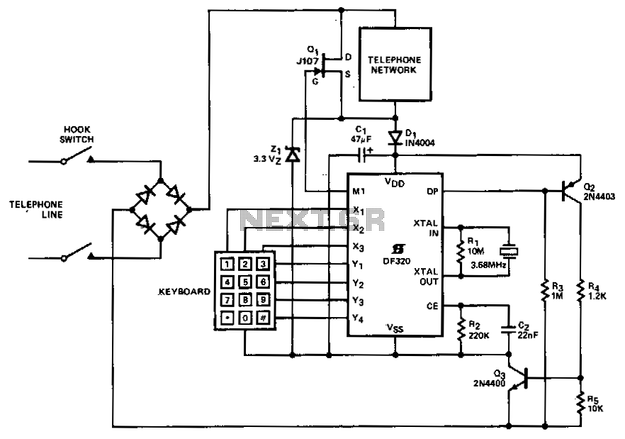
A straightforward method of connecting in series within a telephone set is suitable for PABX or short line applications. When the telephone handset is lifted, capacitor C1 is charged through diode D1 to (Vz1 - 0.7) V, initiating a...

Often, there is a need for an additional telephone ringer in an adjoining room to be alerted about incoming calls. For instance, if the telephone is situated in the drawing room, an extra ringer may be required in the...
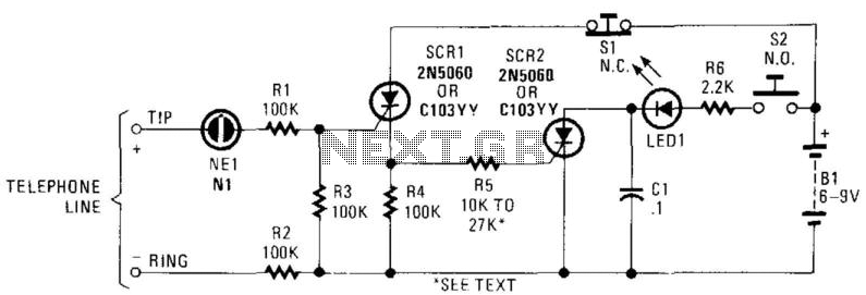
In this circuit, the ringing voltage on a telephone line causes NE-1 to break over, triggering SCR1, which in turn triggers SCR2. If a call has been received, depressing S2 will cause LED1 to light. Depressing S1 resets the...
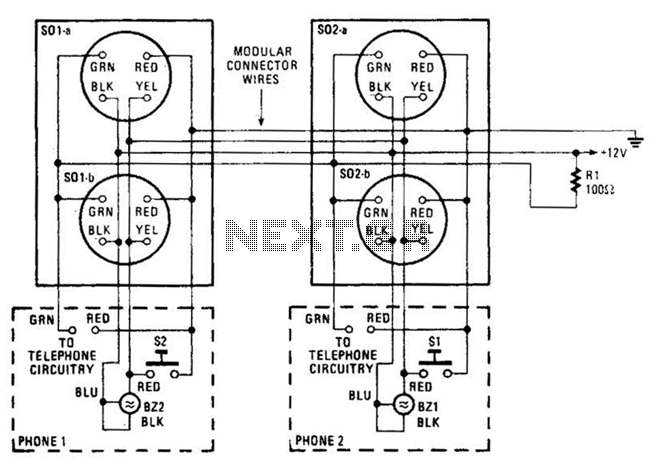
An intercom utilizing dual-modular wall jacks is depicted in this circuit. If the wires are accessible in the home telephone cable, this system can be installed with minimal difficulty. The intercom system described employs dual-modular wall jacks, which are standard...
The Link circuitry is simple and efficient, employing just two ICs, half a dozen transistors, and a handful of garden variety components. It all runs on 12 volts and is easily assembled. You can have your own home intercom...
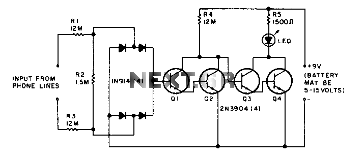
The LED flickers when the phone is ringing or being dialed. It glows steadily when the phone is off the hook. The described circuit involves an LED indicator that serves two primary functions based on the state of the phone....