
Telephone Ringer using 556
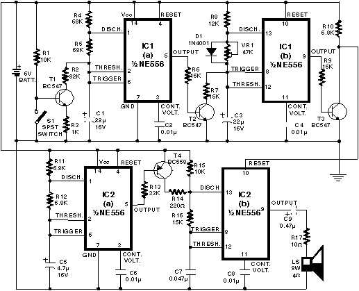
The described circuit utilizes two 556 timer ICs, which are dual versions of the popular 555 timer, to generate a series of modulated rectangular waveforms that mimic the ringing tones of a telephone. The astable multivibrator configuration is used to create the necessary waveforms, with the first multivibrator generating a pulse train characterized by a 1-second low state followed by a 2-second high state. This output governs the operation of the subsequent multivibrator, which further modulates the waveform to produce distinct ringing tones.
The circuit's design incorporates a resistor (R7) connected to the collector of transistor T2. This resistor plays a crucial role in maintaining a charge on capacitor C3, ensuring that it does not fully discharge when T2 is in a conducting state. This design consideration is essential for maintaining the integrity of the waveform generation.
The preset resistor (VR1) is adjustable and must be configured to yield two distinct ringing tones within a one-second interval, allowing for a customizable ringing pattern. The other two multivibrators are tasked with generating additional tones that correspond to the initial output pulses, creating a layered ringing effect.
Activation of the circuit is achieved by closing switch S1, which results in the cutoff of transistor T1, thereby initiating the pulse generation from the first multivibrator. It is important to note that if switch S1 is integrated into the power supply line, there may be a delay before the ringing tones commence, as the circuit requires time to stabilize.
While the circuit is designed to generate ringing tones, it is not intended for direct connection to telephone lines. Instead, it can be adapted for use with intercom systems or similar applications by implementing appropriate drive circuitry across switch S1. This ensures that the generated ringing pulses can effectively signal the intended recipient while maintaining a constant voltage level necessary for operation.Using modulated rectangular waves of different time periods, The circuit presented here produces ringing tones similar to those produced by a telephone. The circuit requires four astable multivibrators for its working. Therefore two 556 ICs are used here. The IC 556 contains two timers (similar to 555 ICs) in a single package. One can also assemble this circuit using four separate 555 ICs. The first multivibrator produces a rectangular waveform with 1-second low duration and 2-second high duration.
This waveform is used to control the next multivibrator that produces another rectangular waveform. A resistor R7 is used at the collector of transistor T2 to prevent capacitor C3 from fully discharging when transistor T2 is conducting. Preset VR1 must be set at such a value that the two ringing tones are heard in one second. The remaining two multivibrators are used to produce ringing tones corresponding to the ringing pulses produced by the preceding multivibrator stages. When switch S1 is closed, transistor T1 cuts off and thus the first multivibrator starts generating pulses.
If this switch is placed in the power supply path, one has to wait for a longer time for the ringing to start after the switch is closed. The circuit used also has a provision for applying a drive voltage to the circuit to start the ringing.
Note that the circuit is not meant for connecting to the telephone lines. Using appropriate drive circuitry at the input (across switch S1) one can use this circuit with intercoms, etc. Since ringing pulses are generated within the circuit, only a constant voltage is to be sent to the called party for ringing.
🔗 External reference
Related Circuits
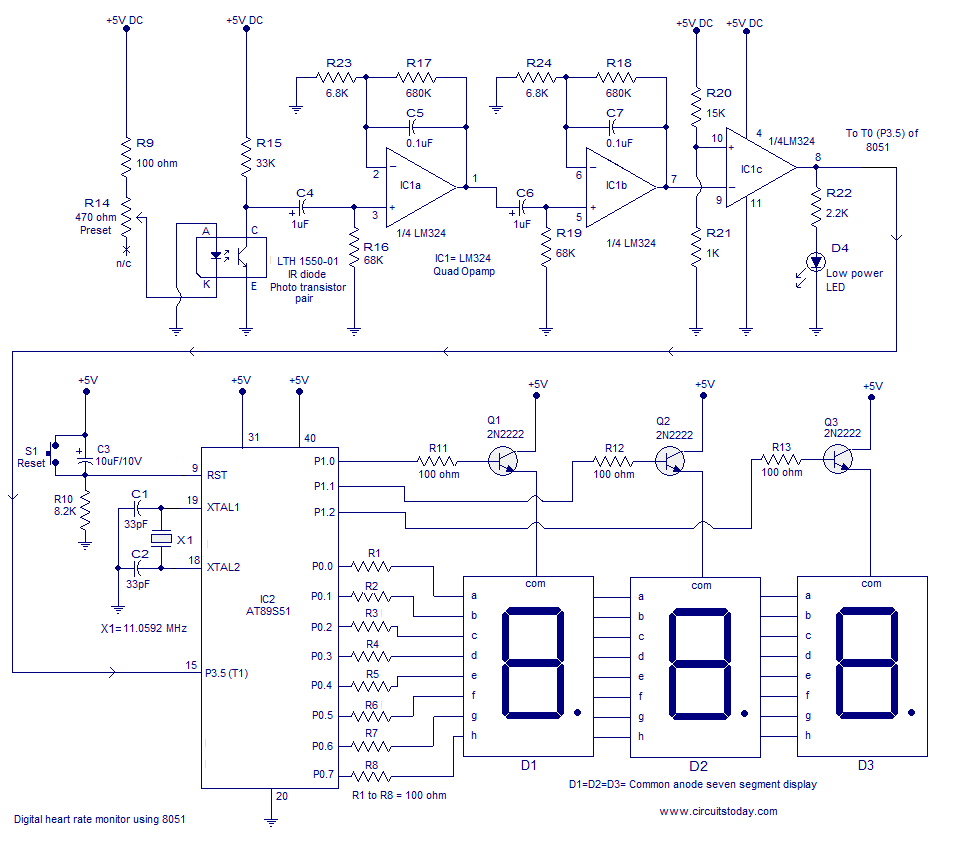
Heart rate monitor using an 8051 microcontroller. It measures the heart rate from the fingertip using an IR diode and phototransistor pair (Photoplethysmography). The AT89S51 microcontroller is utilized in this application. The heart rate monitor circuit operates based on the...
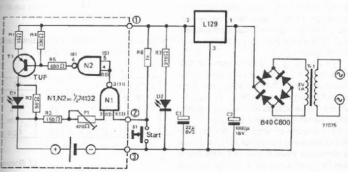
The maximum charge voltage is set at 1.45 volts, while the higher trigger threshold is approximately 1.7 volts. This voltage can be adjusted using potentiometer P1 to reach 1.45 volts. A TTL control signal is output by the voltage...
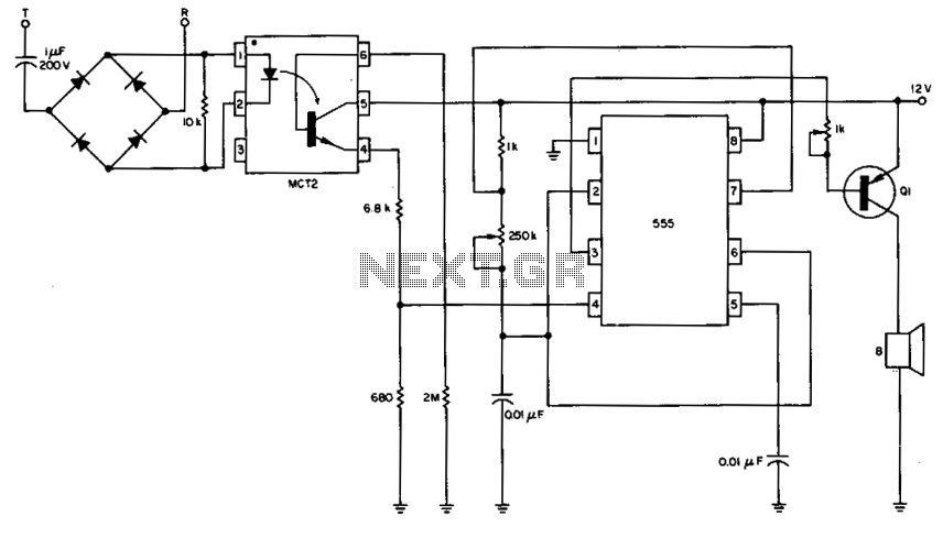
The 555 timer is configured as a multivibrator in conjunction with an opto-isolator to drive a remote speaker. The circuit utilizes the 555 timer in astable mode to generate a continuous square wave output. This output is then used to...
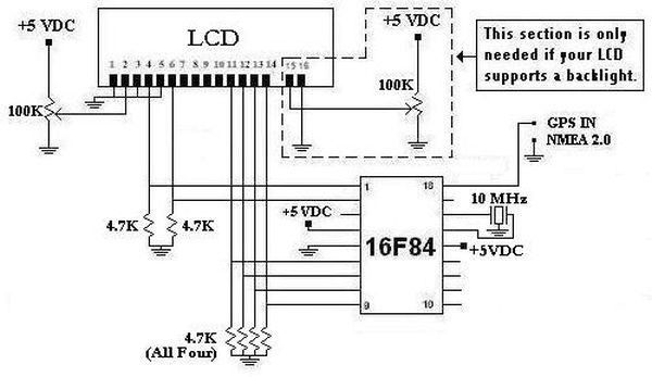
This project was initiated in late 2003 with the aim of learning PIC programming. The goal was to create a functional device that performed a specific task. The project involves the design and implementation of a microcontroller-based system utilizing a...
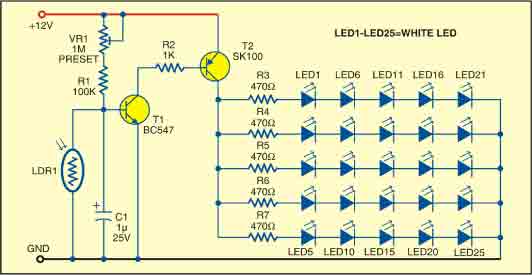
This sunlight-controlled lamp utilizes a light-dependent resistor (LDR) as the sunlight sensor and comprises a total of 25 high-brightness white LEDs. Each row of LEDs is connected in series with separate resistors. The operation of the circuit is straightforward....
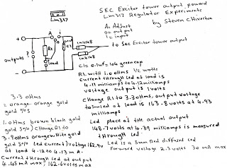
The following experiment demonstrates how Mr. Steven successfully extracted free energy from air using his home-built secondary exciter coil tower. He utilized this energy to power a small LM317 power supply unit. During the process, he hand-wound his coils...