
televition transmitter
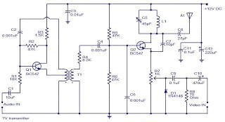
The described system integrates several key components to facilitate video transmission and monitoring during a rocket's flight. The camera's dual orientation capability enhances the ability to capture critical flight data and environmental conditions. The optional external mirror provides flexibility in camera positioning, allowing for downward viewing during lift-off, which is particularly useful for documenting the launch process.
The Yagi antenna, known for its directional capabilities, is optimized for the 1.25-1.30 GHz frequency range, ensuring efficient signal transmission and reception. This choice of antenna is crucial for maintaining a stable communication link between the rocket and the ground station, especially as the rocket ascends and descends through various atmospheric layers.
The electronics package, securely mounted beneath the nose cone, houses the necessary circuitry for video processing and transmission. The design allows for the rocket to deploy its payload effectively once it reaches apogee. The reliance on gravity for deployment simplifies the mechanism and reduces the potential for mechanical failure.
AM modulation used for video transmission is a standard technique that allows for the inclusion of an audio signal, providing comprehensive data for analysis. The DCNV-1300 down converter is an essential component that translates the 1.3 GHz signal to an intermediate frequency, making it compatible with standard VHF TV receivers. This feature enables real-time monitoring of the rocket's flight and descent, facilitating immediate feedback and data acquisition during the mission.
Overall, this system represents a sophisticated integration of aerospace engineering and electronics, aimed at enhancing the capabilities of rocket-based observational missions.The orientation of the camera at launch is looking out the side of the rocket and during descent on the parachute, it is looking down. To allow the camera to look down during lift off, an external mirror can be optionally added. Located in the nose cone of the rocket is the transmitter antenna which is a Yagi style and specifically made for 1.
25-1 . 30GHz band. Packaged in a unit that is just below and is attached to the nose cone are the electronics. Once the rocket itself is suspended on its own parachute, it slides out of the front payload bay of the rocket. This system can be deployed at apogee with only gravity required. For the video, AM modulation is used that contains an input for the sound carrier. The DCNV-1300 down converter was selected in order to receive the 1. 3GHz TV signal. To enable viewing on a standard VHF TV receiver, it converts the 1. 3GHz TV signal down to an intermediate frequency for chan-3 or chan-4. 🔗 External reference
Related Circuits
The modification presented involves using a 2N2219 NPN transistor to replace T2 and a 2N3553 NPN transistor to replace T3. Both transistors are categorized as VHF transistors. It is necessary to attach a heatsink to the last transistor. No...
The 2.25-MHz oscillator Q1 drives amplifier Q2 and XTAL1, an ultrasonic transducer. The transducer is a lead zirconate-titanate type. Taps on T1 and T2 provide low-impedance drive points. The circuit consists of a 2.25-MHz oscillator (Q1) that serves as the...
Output transformer core sourced from a flea market, light blue in color, marked as A-438281-2-9H9-3, with an outer diameter of 47 mm, an inner diameter of 24 mm, and a height of 13 mm. No data is available regarding...
This project is straightforward to construct and will transmit high-quality sound within the FM band (88-108 MHz). An important component is that the... This project involves the design and construction of a simple FM transmitter capable of broadcasting audio signals...
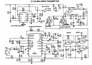
A 27MHz NBFM transmitter circuit schematic featuring the MC2833 and two MPF6660 FET transistors. Utilizing the Motorola MC2833 one-chip FM transmitter along with several supporting components and an MPF6660 RF amplifier, this transmitter can deliver up to 3W into...
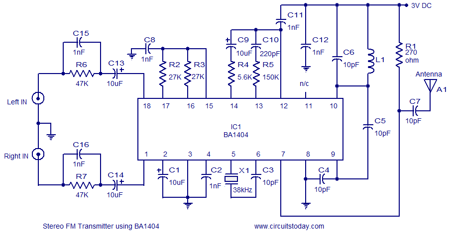
A high-quality stereo FM transmitter circuit is presented. This circuit utilizes the BA1404 integrated circuit from ROHM Semiconductors. The BA1404 is a monolithic FM stereo modulator that incorporates a stereo modulator, FM modulator, and RF amplifier circuitry. The FM...