
27MHz NBFM Transmitter
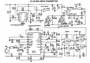
The 27MHz NBFM transmitter circuit is designed around the Motorola MC2833, which integrates key functionalities for FM transmission, simplifying the overall design and reducing the number of discrete components required. The MC2833 is a versatile FM transmitter IC that provides modulation capabilities and is optimized for low power consumption, making it suitable for various applications.
In this circuit, two MPF6660 FET transistors are employed as RF amplifiers. These transistors are known for their high gain and low noise characteristics, which enhance the overall performance of the transmitter by improving signal strength and clarity. The configuration allows for efficient amplification of the modulated signal before it is transmitted through the antenna.
The circuit operates at a nominal frequency of 27 MHz, which is commonly used for various communication applications. However, the design allows for slight variations in frequency, enabling operation in the range of 29 to 32 MHz. This flexibility is advantageous for adapting to different transmission requirements or regulatory constraints.
The output stage of the transmitter is designed to deliver up to 3 watts of power into a 50-ohm load, which is typical for radio frequency applications. This output power level is sufficient for short-range communication and can effectively drive a standard 50-ohm antenna, ensuring efficient radiation of the RF signal.
Supporting components in the circuit may include resistors, capacitors, and inductors, which are essential for tuning the circuit, stabilizing the operation, and ensuring proper modulation. The schematic will typically include details on the values and types of these components, which are critical for achieving the desired performance.
Overall, this 27MHz NBFM transmitter circuit represents a compact and efficient solution for FM transmission, leveraging the capabilities of integrated circuits and discrete components to deliver reliable performance in a range of applications.A 27MHz NBFM transmitter circuit schematic with MC2833 and 2 FET transistors MPF6660. Using a Motorola MC2833 one-chip FM transmitter, a few support components and am MPF6660 RF amp, this transmitter delivers up to 3W into a 50 ? antenna. It is capable of operation over about 29 to 32 MHz with the components shown. 27MHz NBFM transmitter circuit diagram.. 🔗 External reference
Related Circuits
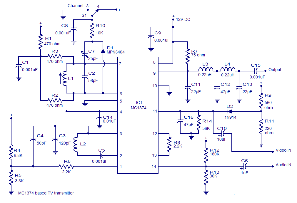
A very simple and high-quality TV transmitter circuit based on the IC MC1374 is presented in this article. The MC1374 is an integrated TV modulator circuit suitable for various TV transmitter applications. It encompasses all necessary circuitry required for...
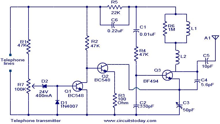
This circuit is a simple yet effective design for transmitting telephone conversations. When the telephone receiver is on-hook, the voltage across the lines is approximately 48 volts. The preset resistor R7 is adjusted to achieve a voltage of 24.7...

This is a simple circuit design for a video transmitter capable of radiating signals up to 50 meters. The video transmitter can be connected to a camera as a source and allows viewing on a VHF channel analog television....
Maxim has introduced a series of five integrated oscillator building blocks in the MAX260x series, covering a frequency range of 45 to 650 MHz. The MAX2606 is designed for the VHF band, allowing frequency variation of approximately ±3 MHz...
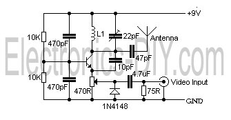
This is a simple video transmitter capable of transmitting signals up to 50 meters. It can be utilized with cameras or other video sources and allows viewing on VHF channel analog televisions. The video transmitter operates on a supply...
This circuit is a basic design that includes indicator LEDs and appropriate resistor values. A dotted line indicates that the IR LED is connected to the circuit via a length of wire (in this case, a telephone cable). The...