
Temperature and Humidity Logging Over Ethernet I
The circuit design for this temperature and humidity logging system includes several key components: the ATmega328P microcontroller, the SHT21 temperature and humidity sensor, and the ENC28J60 Ethernet module. The ATmega328P is configured to operate at 3.3V, which aligns with the power requirements of both the SHT21 sensor and the ENC28J60 module. The SHT21 sensor is connected to the microcontroller via the I2C interface, utilizing pull-up resistors on the SDA and SCL lines to ensure proper signal integrity. If a 5V microcontroller is used, an I2C level translator must be incorporated to safeguard the sensor from overvoltage.
The ENC28J60 module connects to the ATmega328P through the SPI interface, which includes connections for the chip select (CS), master out/slave in (MOSI), master in/slave out (MISO), and serial clock (SCK) lines. Proper decoupling capacitors should be placed near the power supply pins of both the ENC28J60 and the ATmega328P to mitigate noise and voltage spikes. The microcontroller firmware should manage the Ethernet connection, handle data logging, and implement the power cycling mechanism to reset the modules periodically.
In order to facilitate real-time data streaming, the firmware must also include a mechanism for handling incoming requests and ensuring that the Ethernet module does not become unresponsive. This may involve implementing a state machine to track the status of requests and manage the timing between them effectively. By establishing a robust communication protocol, the system can ensure reliable data transmission while minimizing the risk of collisions that could lead to unresponsiveness. Overall, this temperature and humidity logging project represents a significant improvement over previous designs, offering enhanced functionality and real-time data access capabilities.A project on temperature/humidity logging a couple of years ago. In that project I logged the temperature and humidity readings in my basement lab over the course of a year. One issue with the approach I took back then was that the data could not be observed in real time because the logged data were written to an SD card and could only be re
trieved once the logging process was done. So naturally this time around I wanted to build a data logger with better capabilities. One way to obtain real time data is to stream the logged data over the Ethernet so that the data can be logged, processed and then displayed on a PC. And this is the approach I took. The Ethernet chip Arduio officially supports is WIZnet`s W5100. But it seems that Microchip`s ENC28J60 based controller boards can be had at a much lower price point and several libraries (like this one ) already exist so I decided to give that a go.
The temperature/humidity sensor I used in this project is Sensirion`s SHT21. I have used it in many of my projects before and it is very easy to use with various libraries readily available. One thing to note is that the maximum Vcc for SHT21 is around 3. 3V. So if you were to use 5V on your MCU, an I2C level translator (i. e. TI`s PCA9517 ) needs to be utilized in order to avoid damage to the sensor. The ENC28J60 module I used can be obtained on eBay for less than $5. Since both the sensor and the Ethernet module operate at 3. 3V, it is much easier to power the MCU at 3. 3V as well so that we do not have to worry about voltage level translations. While ATmega328p is not rated to run at 16Mhz at 3. 3V, in normal cases this shouldn`t be an issue. Since the default Arduino fuse settings assume a 5V supply voltage, you might need to adjust the fuse settings in situations where the load can change rapidly and the power supply is not able to maintain a steady 3.
3V output. But for this particular application, the current draw is pretty stable at around 120mA so as long as a regulated power supply is used, no additional changes are necessary for the MCU to run at the lowered voltage. One thing I found out after putting the circuit together is that the ENC28J60 would somehow become unresponsive after a while (sometimes a couple of hours, sometimes a little bit longer).
After googling around, it appeared that this was caused by the limitations of the ENC28J60 library code and would happen when a new request is made while there is still a pending request. This certainly sounds like a plausible explanation. Since request collisions cannot be easily avoided (increasing the interval between requests will help somewhat but won`t eliminate the problem as we do not have control over all the other devices connected to the same network), this shortcoming is certainly a big problem for a data logger that is supposed to be working 24/7.
So how do we resolve this Obviously we could go through the library code and make appropriate changes to make it more robust. But this would be a rather daunting task given the lengthiness of the specifications and the complexity of the code.
I may eventually get to this but it is certainly not something that can be achieved in a couple of days` time frame for sure. There are always two ways to tackle a problem: one is to solve it and the other is to avoid it. Since solving the issue from a coding standpoint is rather complicated, this leaves me with the latter option.
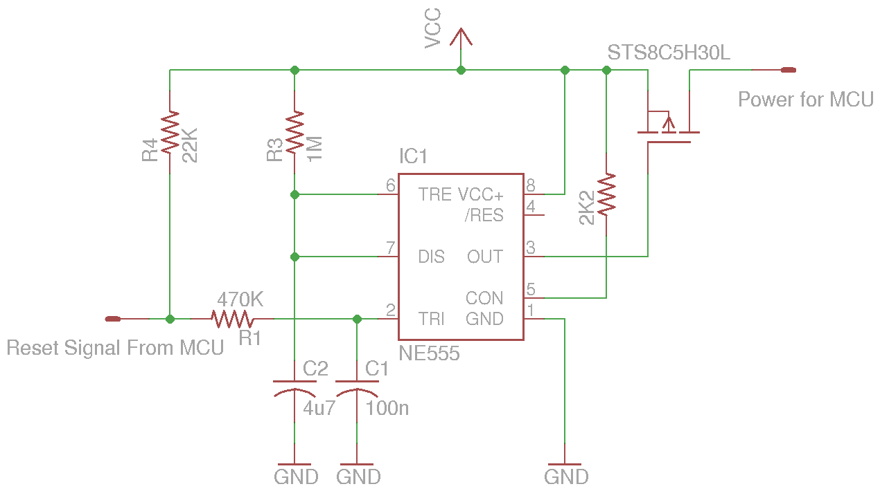
My solution to the problem is actually quite simple. Since the Ethernet module may hang once a couple of hours at the most, communication can be re-established if we just simply power cycle the MCU and the Ethernet module (e. g. turning off and on) and if we set the power cycle interval to be once per hour, we can pretty much guarantee that the Ethernet interface will never be stuck in the unresponsive state.
Should the Ethernet module hang, we could always count on the next reset to bring 🔗 External reference
Related Circuits
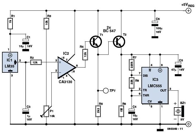
The circuit utilizes a precision integrated temperature sensor, the LM35 (IC1), which provides a linear and directly proportional output in millivolts over a temperature range of 0 to +155 degrees Celsius. This sensor can be incorporated into fire smoke...
This circuit controls a load, specifically a DC brushless fan, based on temperature compared to a setpoint. The transducer used is a diode operating in the forward polarization regime. When forward-biased, the forward voltage drop across the diode exhibits...
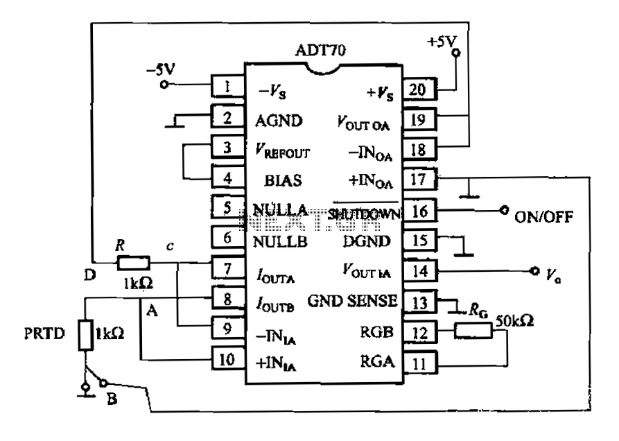
The AD170 basic electrical parameters include a temperature coefficient of 25 ppm/°C and a temperature measurement accuracy of ±1°C, with a maximum temperature range of -200°C to +100°C. The power supply required is +5V or -5V, and the operating...
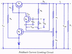
If the load resistance (RL) is reduced or the load terminals are accidentally shorted, a very large load current will flow, potentially damaging the pass transistor (Q1), diode, or other components. Fuse protection may not be sufficient, as the...
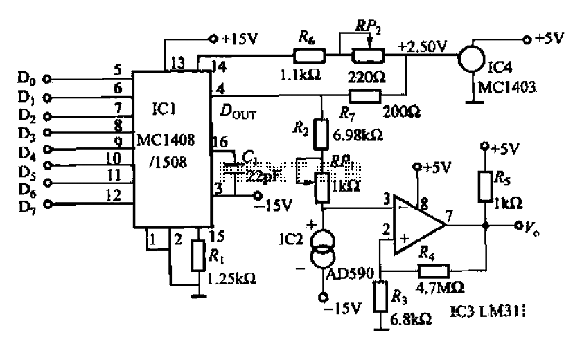
An 8 NC temperature adjusting circuit is presented, primarily composed of a D/A converter, a reference power supply, amplification components, temperature sensors, and other necessary elements. This circuit regulates the temperature within a range of 0-51°C and is suitable...
The Boss SD-1 Super OverDrive is a pedal characterized by a straightforward design, incorporating a dual operational amplifier (uPC4558C) and six transistors, along with an asymmetric overdrive circuitry that emulates the classic, natural growl of a tube amplifier. It...