
Temporarily Silencing A Smoke Detector

The circuit design consists of several key components working in tandem to achieve the desired functionality of silencing the smoke detector. The Mosfet (Q3) serves as an electronic switch, effectively controlling the power supply to the smoke alarm. It is critical to ensure that the Mosfet is correctly wired to allow for immediate restoration of the smoke alarm's operation upon disconnection of the silencing circuit. The use of a 3-core data cable and a 3.5mm stereo plug facilitates a reliable connection between the silencer circuit and the smoke alarm, ensuring that the system can be easily installed or removed as needed.
The monostable configuration of IC1 is pivotal in managing the timing for the silencing operation. The 555 timer's ability to generate a precise timing sequence allows for effective control of the silencing period, ensuring that the smoke detector remains inactive for the predetermined duration without user intervention. This feature enhances user convenience and reduces the likelihood of accidental reactivation during the silencing period.
The astable multivibrator configurations of IC2 and IC3 further enhance the functionality of the circuit by providing visual and auditory feedback. The flashing LED serves as a clear indicator that the silencing mode is active, while the piezo buzzer offers an unobtrusive alert at intervals, ensuring that the user remains aware of the circuit's status without being overwhelmed by noise.
Overall, this circuit represents a sophisticated solution for managing smoke detector alarms, combining user-friendly features with reliable performance to enhance safety and convenience in everyday scenarios.It provides a means of temporarily silencing a battery-powered smoke detector after you`ve burnt the toast, scorched the baked beans or whatever! Unlike the earlier design, this more sophisticated version does not cause strange chirps and whistles to emanate from the smoke detector towards the end of the silenced period.
It also flashes a LED and produces a series of short, unobtrusive tones from its inbuilt buzzer while it is active. A separate 9V (or 6V) battery is required to power the circuit, which is mounted remotely from the smoke alarm. Connection to the alarm is made via a 3-core data cable terminated in a 3. 5mm stereo plug, while a matching switched socket is fitted to the alarm`s casing. In addition to the socket, only three other components are installed inside the smoke alarm. These are Mosfet Q3, its 100W gate resistor and 15V zener diode ZD1. These parts can all be mounted on a small section of prototyping board or soldered point to point from the socket terminals.
The Mosfet is wired in series with the smoke alarm`s negative battery lead and acts as a switch. As shown, the contacts of the socket must be wired so that the Mosfet drain-source connections are shorted out when the plug is removed, thus allowing immediate restoration of the smoke alarm to normal operation. When the silencer circuit is inactive, the reed relay (RLY1) is off, so battery power is disconnected from the circuit.
An exception to this is Q3`s 4. 7kO gate pull-up resistor, which is powered directly from the battery. This holds the Mosfet switch on, powering the smoke alarm from its on-board 9V battery. Now consider what happens when the "silence" switch (S1) is pressed. This action applies battery power to the entire circuit through the switch contacts. At the same time, IC1 (which is wired as a monostable) is triggered by a brief pulse on its reset input (pin 2). This initiates the 555`s timing sequence, so its output (pin 3) immediately swings high, switching on Q1 and activating the relay.
A second transistor (Q2) wired to IC1`s output also conducts, pulling Q3`s gate low and switching it off. As a result, the smoke alarm is disconnected from its 9V battery and all of the noise ceases instantly!
When the relay is closed, an additional path exists from battery positive to the circuit`s power rail so that when the switch is released, the circuit keeps running. The circuit then continues to run for the duration of IC1`s timing period (over 8 minutes). The remaining two 555 timers (IC2 & IC3) are configured as astable multivibrators. IC2 is used exclusively to flash an indicator LED at a rate of about once per second. IC3 has a longer period, sounding a piezo buzzer briefly about once every 10. 5 seconds. Use a 5V reed relay when the circuit is powered from a 6V battery and a 12V version when powered from 9V.
Because of the high impedance and low leakage of the Mosfet`s gate, the silencer`s battery can be expected to last almost its shelf life assuming that you don`t burn the toast too often! 🔗 External reference
Related Circuits
The operation principle of the proposed metal detector circuit is straightforward yet intriguing. The detection function is activated by sensing a decrease in the quality factor (Q) of the LC network associated with the circuit when a metal object...
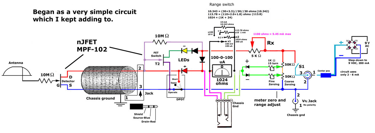
This post discusses the construction of multiple versions of JFET static charge detectors, highlighting observed differences that are not easily explained. The JFET (Junction Field Effect Transistor) static charge detector operates by utilizing the unique characteristics of JFETs to sense...
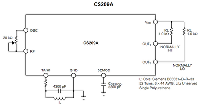
The core component of this DIY metal detector circuit is the CS209A. The metal detector is constructed with a single coil of 100 µH. The CS209A contains an oscillator that forms an LC circuit; the inductance of the coil...

Both oscillators are built using MPF102 or J310 FETs. The Mixer is BF998 dual gate MOSFET. Audio IC amplifier is LM386 which drives a speaker. I have used a stabilized supply for two oscillators and mixer. U1, a 78L05...

The circuit exhibits a typical voltage gain of 84 dB and an automatic gain control (AGC) range of 80 dB. It demonstrates minimal alterations in bandpass shape, generally less than 1 dB tilt for 60 dB compression. There are...

A schematic diagram for a metal detector has been found. The project does not need to be original and can be sourced from the internet. There are several questions regarding this schematic. One query pertains to a small arrow...