
Ten Road temperature itinerant detecting circuit 555 CD4069 CH208
The temperature detection circuit operates through a systematic integration of components that work together to monitor and respond to changes in temperature. The temperature sensor, specifically the 3AX31, is crucial for detecting ambient temperature variations. Its linear response ensures accurate readings, which are then converted into frequency signals by the V/F converter.
The oscillator, utilizing the 555 timer IC, generates a frequency that varies with the changes in resistance of the temperature sensor. This frequency is essential for the subsequent processing stages as it provides a direct correlation between temperature and frequency, enabling precise temperature measurements.
The pulse generator, built with the CD4069 inverter, provides a consistent timing signal that drives the counting mechanism in IC3. The CD4017 counter is designed to sequentially activate its outputs based on the timing pulses, allowing for a systematic approach to monitoring multiple temperature points. Each output corresponds to a specific temperature reading, which is facilitated by the analog switches in IC4.
The phase-locked loop circuit, combined with the audio decoder IC5, serves a dual purpose: it not only processes the frequency signals but also triggers an alarm when the temperature exceeds a set threshold. The adjustable locking bandwidth allows for flexibility in the system's response to temperature fluctuations.
Finally, the decoding display circuit (IC6) provides a visual representation of the temperature status through LED indicators. This feature enhances the usability of the circuit by allowing operators to quickly assess temperature conditions at a glance.
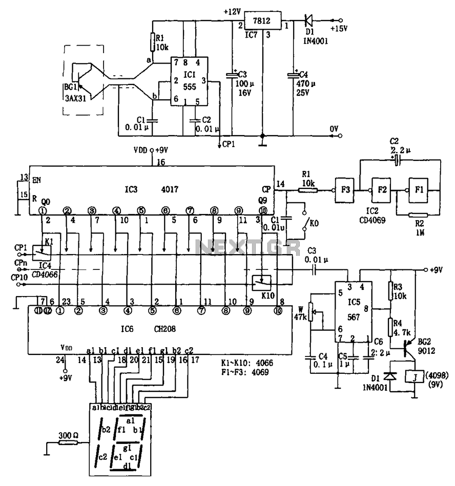
Overall, this temperature detection circuit is designed for reliability and effectiveness in monitoring temperature in critical applications, ensuring timely alerts and facilitating preventive measures in environments where temperature control is essential. As shown in Fig ten temperature detection circuit circuit. The detection circuit by the temperature sensor, V/F converter circuit, an oscillator, circuit testing program contro l, alarm, decoded and displayed circuit. Temperature sensor 3AX31, and diode-connected form. When the ambient temperature changes, the radio - sets and resistance k linearly with temperature changes. Oscillator consists of IC1 (555) and rce, R1, C1 and other components, the oscillation frequency of f 1.44/(R1 + 2rce) C1, it rce changes linearly with temperature, then f accordingly varies in proportion to, in order to achieve temperature/frequency conversion.
If the detected 10 points, need 10 such temperature/frequency converter head. Circuit IC2 use hex inverter CD4069, where F1, F2, F3 composed of 0.2Hz trigger pulse generator, which sends a pulse count CP every 5 seconds to count circuit IC3. IC3 decimal counter/pulse distributor CD4017, under CP effect, its ten output terminal Q0 ~ Q9 successively appear high pulse.
Corresponding analog electronic switch K1 ~ K10 are sequentially turned on. IC4 using analog switches CD4066, K1 ~ K10 frequency signal outputted sequentially fed into the phase locked loop circuit having an audio decoder IC5 (567) pin (IC5 wherein the center frequency is f0 1/1.1RwC4, circuit C5 adjustable given locking bandwidth), when the temperature exceeds a certain limit the scope of the road, and with a preset center frequency f0 are the same, IC5 output low (since feet), making BG conduction, the relay J pull the trigger alarm circuit, alarm anthracene ring. At the same time, Q0 ~ Q9 high signal output of IC3 in turn fed IC6 (CH208) decoding display circuit, after IC6 decode output signal corresponding fields, drive common cathode LED digital tube work, it appears the corresponding point over-temperature field.
The detection circuit is adapted to units, and other train axle temperature detection occasions.
Related Circuits

The circuit illustrates a basic yes/no gas detector. It utilizes three 1.5-V D cells as the power source, with SI functioning as an on/off switch. The heater is powered directly from the battery, while the electrodes are connected in...

This system utilizes an MM5369 integrated circuit (IC) to generate a 60 Hz signal from a television burst crystal operating at 3.579 MHz. The components F8 and V9 produce 10 Hz and 1 Hz signals derived from the 60...
APM-81 lift includes the main circuit, safety circuit, and brake circuit. The APM-81 lift system is designed with a comprehensive electrical architecture that integrates a main circuit, a safety circuit, and a brake circuit, ensuring reliable operation and enhanced safety...

The output level was set to 3.8V peak to peak. The initial objective was to compare several different operational amplifiers (op-amps) before further optimizing the circuit. The op-amps evaluated were the TL072, LM4562, and OPA2134. The distortion spectra are...

This is a battery-powered infrared (IR) link that can be utilized in multiple rooms. The standby current is exceptionally low, resulting in excellent battery life. The circuit is designed to shut down when faced with extraneous IR radiation, effectively...

We are going to build a START-STOP drive (as commonly found in professional tools), that is a circuit with one switch to run the output (an LED in this case) and one switch to stop it. Nutchip feature two...
Warning: include(partials/cookie-banner.php): Failed to open stream: Permission denied in /var/www/html/nextgr/view-circuit.php on line 713
Warning: include(): Failed opening 'partials/cookie-banner.php' for inclusion (include_path='.:/usr/share/php') in /var/www/html/nextgr/view-circuit.php on line 713