
Testing a EM-406A GPS module
The EM-406 GPS module is designed for ease of integration into various applications, particularly in geotagging and navigation systems. The module's integrated antenna simplifies installation, while the SiRF III chipset ensures reliable satellite tracking and accurate positioning. The output of NMEA sentences at a standard baud rate of 4800 allows for compatibility with many serial communication applications.
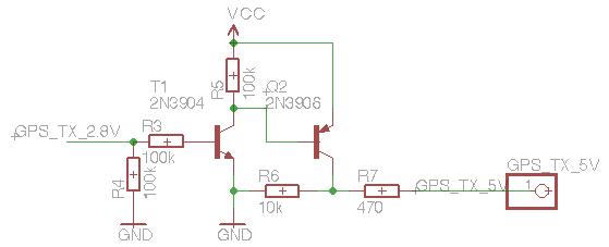
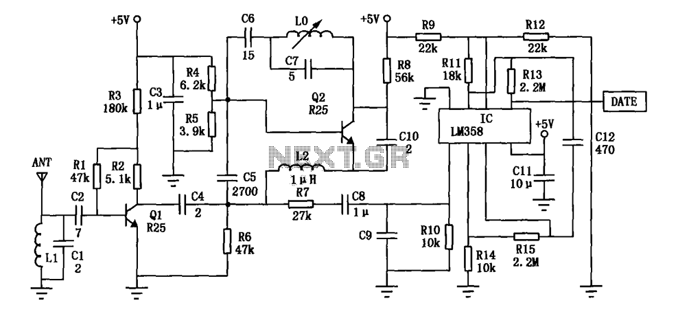
To interface the EM-406 with microcontrollers or other devices that operate at TTL levels, it is crucial to implement a level shifting circuit. This circuit should be designed to convert the 2.8V serial output from the GPS module to a 5V signal that can be safely read by the receiving device. A common approach involves using a transistor-based level shifter or dedicated level shifter ICs, which can effectively translate the voltage levels between the two devices.
When setting up a terminal for data monitoring, the configuration should include the specified baud rate, stop bits, and parity settings to ensure proper communication with the GPS module. This allows users to observe the incoming NMEA sentences in real-time, facilitating debugging and verification of the GPS data being received.
For more advanced applications, utilizing software like SiRFDemo can provide additional functionality, such as visualizing satellite positions and analyzing various parameters from the GPS module. This application can decode the NMEA sentences and present the information in a user-friendly format, enhancing the overall user experience and enabling more effective data utilization in geotagging projects.Some months ago I ordered a EM-406 GPS module from Sparkfun. I intended to explore geotagging and this module seemed to be a simple one to use : integrated antenna, SiRF III chipset (seems to be well know on forums) while not too expensive. You provide a 5V power source and it begins to output NMEA sentences on the TX output at 4800 bauds. When th e led stops blinking the module is fixed : enough satellites are tracked to computes its position as Lat/Long coordinates. One problem is that the serial level is not TTL : 2. 8V instead of 5V. Simply connecting the module TX to the level shifter RX-I is not enough. Another level adaptation is done with the following circuit I found after several days of Google fruitless searches : [Dead link].
The simplest way to test if you can correctly read NMEA sentences on your PC is to launch the Terminal configured with the following parameters : 4800 bauds, 1 stop-bit, no parity. To go further and actually see the content of the data sent by the GPS module, the SiRFDemo application is very helpful (
🔗 External reference
Related Circuits
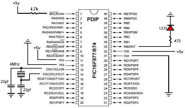
PIC development/testing board. This is a PCB design for a basic PIC16F877 development board. All that is required is a 4 MHz crystal, two 22 pF capacitors, and one 4.7 kΩ resistor. The PIC16F877 development board is designed to facilitate...

Circuits of this type are designed to drive LED arrays to enhance visibility and conspicuity when a vehicle is stopped or slowing down. This specific circuit emits a visual alert signal consisting of four short flashes followed by a...
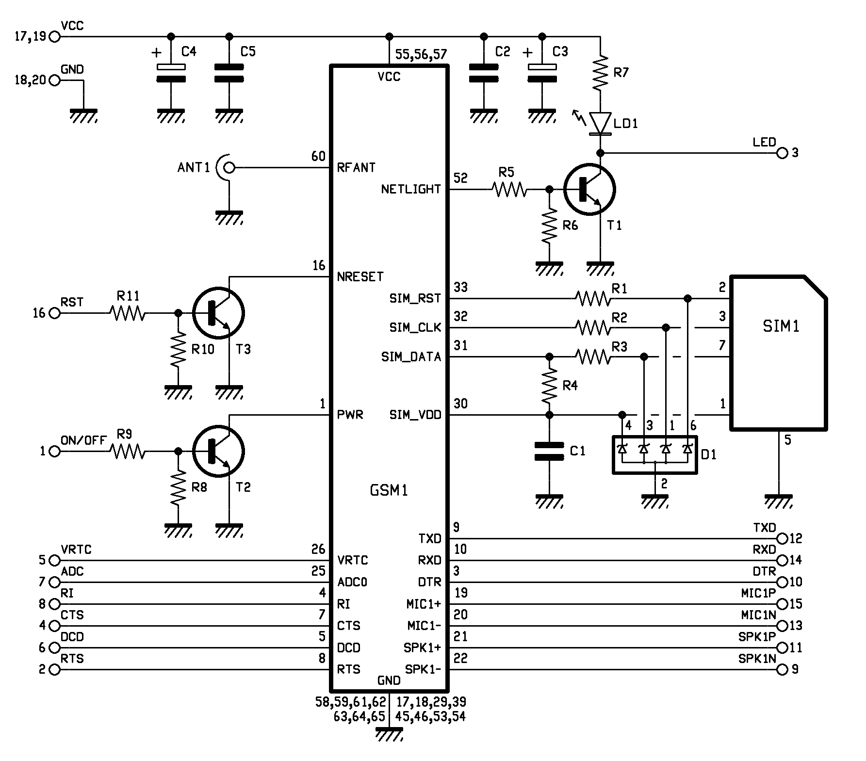
The printed circuit board features a 10-pin by 2-pin strip used for connection with the circuit board of the remote control device. Pin 1 (ON/OFF) is utilized by a microcontroller to control the power state of the GSM module....
The GPS interface can be fed in 2 ways: with a stabilized 5V supply or with a 10 to 25V unregulated DC supply. In both cases, the power is fed into the RJ45 connector on point 8. Pin 7...
The DF data transmission module operates at a frequency of 315 MHz and utilizes a surface acoustic wave (SAW) resonator for frequency stabilization, ensuring high frequency stability. The frequency drift remains minimal, at only 3 x 10^-6, across a...
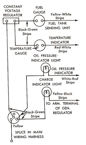
The fuel and temperature gauges used in the 1960-1965 Ford Falcon are basic instruments whose operating principles have become obscure in today's digital electronics era. To effectively troubleshoot the circuits, an analog voltmeter and two "D" cell batteries are...