
The 145 Theremin

The 145 theremin represents an evolution in theremin design, incorporating differential-pair oscillators that enhance both performance and sound quality. The choice of operating frequencies at 270 kHz for volume modulation and 360 kHz for pitch modulation ensures that the instrument maintains a wide dynamic range while allowing for precise control over pitch and volume. The improved pitch-arc linearity is a significant advancement, making the instrument more intuitive for performers, as they can achieve desired pitch changes with less hand movement.
The use of silicon rectifiers as varactors is a cost-effective solution that contributes to the overall tuning flexibility of the theremin. With a tuning range of 1200 Hz for volume and 700 Hz for pitch, musicians can explore a wide array of tonal possibilities. The ±10 percent frequency variation among different units indicates the importance of careful calibration and quality control during manufacturing.
In terms of signal processing, the output derived from the resonant L-C pairs is crucial for producing low-distortion sine waves, which are essential for maintaining the purity of the theremin's sound. The weak coupling mechanism implemented through components C8 and R10 ensures that the pitch oscillators can achieve a stable zero-beat condition, which is vital for maintaining pitch accuracy when the performer’s hands are not in proximity to the instrument.
The design also addresses the mixer input levels, which are intentionally unequal to reduce the output amplitude. This strategic approach minimizes potential distortion and enhances the overall tonal quality of the theremin, setting it apart from previous models like the 144. Overall, the 145 theremin showcases advancements in electronic design and engineering, resulting in a more refined and versatile instrument for musicians.Since the publication of the type 144 theremin project article in September, 1998, many of them have been successfully constructed. As in the 144, and its forerunner, the Southwest Technical Products model 142, the 145 theremin retains a heterodyne topology similar to that used by Mr.
Theremin in his original instruments. The 145 theremin is similar to the 144 in most respects, excepting the types of oscillators used. The 145 theremin oscillators are differential-pair types, in comparison to the Colpitts types in the 144. The approximate operating frequencies for the 145 theremin are 270kHz for the volume circuit and 360kHz for the pitch circuit.
Compared to the 144, the 145 has improved pitch-arc linearity, with A440 occurring at about 10 inches of hand distance, compared to about 5 inches for the 144. The practical pitch range for the 145 is about 4 1/2 octaves. Inexpensive silicon rectifiers are used as varactors to provide a volume oscillator tuning range of about 1200Hz and a pitch reference oscillator tuning range of about 700Hz.
These frequencies will typically vary within ±10 per-cent among instruments, due to tolerances. In the new design, oscillator outputs are taken from the resonant L-C pairs, and are low-distortion sine waves. Weak coupling is provided between the two pitch oscillators via C8 and R10 to induce a "lock" condition for zero-beat when the pitch hand is absent.
The pitch oscillator levels at the mixer input are unequal, and the mixer output amplitude is significantly reduced in comparison to the 144. This reduct 🔗 External reference
Related Circuits
The principle of operation of the RCA Theremin is based on the beat frequency oscillator. The frequency of one oscillator can be varied by the change in capacitance caused by the movement of the hand towards or away from...
The 203 Theremin employs Wien-bridge oscillators in a heterodyne configuration to create an audible tone that varies with hand position. It operates on a 9-volt battery, ensuring convenience and safety within a compact enclosure. This instrument is a pitch-only...
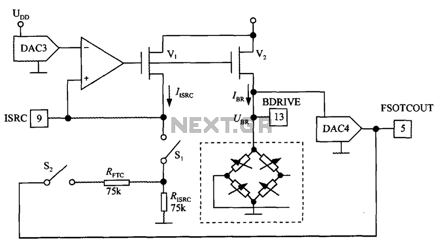
The excitation circuit for the digital pressure signal conditioner MAX1458 is illustrated. The output DAC3 is utilized to adjust the sensor excitation current (IBR), enabling full-scale fine calibration. The reference current (IISRC) is determined by the resistor RISRC and...
This circuit utilizes a JFET to receive signals from an LED and buffer them. The output voltage is managed using an IC 1458 or LM1458, which provides approximately 7 volts in darkness and experiences a drop of about 2...
The circuit mentioned is significantly less effective than Lev's Oscillator for Theremin applications. The simulation waveforms indicate the red sine wave represents the voltage on L1:A, the black sine wave indicates the voltage on Q1:D, and the blue square...
This was a quick experimental prototype based on a simple design by Doug Forbes, which utilizes common vacuum tubes. In its simplest form, a theremin operates by mixing two high-frequency oscillators—one fixed and the other tuned by the capacitance...