
studio synth circuit
The Cerberus filter is a sophisticated audio processing unit designed to provide a versatile range of filter types suitable for various applications in sound synthesis and manipulation. Utilizing the LM13700 OTA, the circuit comprises four filter stages arranged in a serial configuration, each contributing to the overall lowpass filtering effect. The inclusion of a voltage-controlled resistor in the design allows for dynamic control over the filter's response, enabling users to adjust the cutoff frequency in real-time.
The design incorporates a buffered configuration between each filter stage, which is a significant advantage of the LM13700. This buffering ensures signal integrity and minimizes distortion that could arise from loading effects in subsequent filter stages. The resulting 4-pole lowpass filter is characterized by its ability to attenuate higher frequencies while allowing lower frequencies to pass, which is essential for creating rich, warm tones typical of analog synthesizers.
To expand the filter's capabilities, the implementation of highpass and bandpass filters is achieved through a clever subtraction method. By taking the lowpass output and subtracting it from the input signal, a highpass filter response is generated. The bandpass filter is derived from the output of the second filter stage, resulting in a unique filter response that emphasizes certain frequency ranges, making it ideal for various sonic applications.
The resonance feature of the Cerberus filter is particularly noteworthy. By incorporating diodes in a soft-clipping configuration, the filter can produce a pleasing distortion effect when the feedback gain is increased. This allows for creative sound design possibilities, as users can push the filter into self-oscillation for more aggressive sounds. The potentiometer integrated into the feedback path provides users with the flexibility to control the amount of resonance, enabling a wide range of tonal variations.
In summary, the Cerberus filter is a versatile and powerful tool for sound synthesis, offering multiple filter types and a distinctive resonance characteristic that can enhance the creative process for musicians and sound designers alike. Its design leverages proven techniques from established filters while introducing unique features that expand its functionality in a modern context.I originally wanted to call it Chimera , but then I remembered there`s already a synth company using that name, so I went with Cerberus to avoid confusion, and because Tricephalic Filter just doesn`t have the same ring to it. I didn`t bother renaming the mp3 ²s below. But I digress Like its namesake, this filter has three heads , or in this case, filter modes. The main influences here were RenG© Schmitz` Late MS-20 Filter, Osamu Hoshuyama`s VCF 1984B and fake SSM2040 VCF, and Ray Wilson`s VCSVF (this was another reason I wanted to use Chimera, to mark it as a composite beast- oh well). Like all of these filters (as well as many others), the Cerberus is based on OTA`s (Operational Transconductance Amplifiers)- in this case, the LM13700.
The LM13700 datasheet contains a schematic for a single-ended voltage controlled resistor, which is how it`s being used here- in fact, the circuit used in the filter(s) is not much different from the application circuit shown in the datasheet. Each filter stage (of which there are four here) consists of one such VC resistor as part of an R/C filter network, with each stage buffered before going on to the next.
This is a handy thing about the LM13700- it includes a buffer for each OTA on the chip. These four stages arranged in a serial configuration give us the core of a 4-pole lowpass filter. That`s cool, but what if we want other filter types This is where Ray Wilson`s filter comes in. Nice guy that he is, he explains how his VCSVF works quite well at his site. In a nutshell, the highpass filter is achieved by subtracting the lowpass signal from the input, and the bandpass is the highpass signal through the first filter stage. This actually creates a BPF which is steeper on the highpass side than the lowpass side. Since the Cerberus filter has four stages instead of two, we`ll use the second filter stage instead of the first for this.
On to the resonance. This is, in my opinion, what makes a filter. I noticed that the RenG© Schmitz filter, as well as other MS-20 clones and similar filters, uses the trick of using diodes (green LEDs here, I also tried red) in a soft-clipping configuration, like many distortion stompboxes. I decided to give it a try here as well (with the amplifier part configured a bit differently)- works great.
I added a potentiometer to the feedback path so you can increase the gain for more distortion. There is another interesting thing about the MS-20-style filter resonance, which is that it is returned through the first stage capacitor, which means the feedback is, in effect, bandpass filtered. Ray Wilson`s filter goes about this in ath the feedback being LEDs), to add another podown and the bandpass cwhile I gather the restlay this audio clip.
rd at a 90-degree angle- this daughterboard also contains the main IC/ROn of the main board, hay enough to try on breadboard quick 🔗 External reference
Related Circuits
This circuit prioritizes a microphone and preamplifier (voice circuit) over any other audio signal, functioning similarly to a one-way intercom. When the push-to-talk switch is activated, the main amplifier switches from music to the voice signal. Essentially, a voice-over...
A highly effective 1-watt FM transmitter circuit that is easy to construct. The circuit consists of four transistors: one functions as a stable oscillator, followed by a buffer stage to maintain frequency stability during adjustments. Next is a resonance...
A sawtooth wave generator circuit using a 555 IC is presented in the article below. The frequency equation is provided with the supply voltage Vcc. The sawtooth wave generator circuit utilizing a 555 timer integrated circuit (IC) is a fundamental...
Automatic Gain Control (AGC) is a circuit design that maintains a consistent level of amplification for sound or radio frequency signals. If the signal is too low, the AGC increases the gain to ensure the output remains at a...
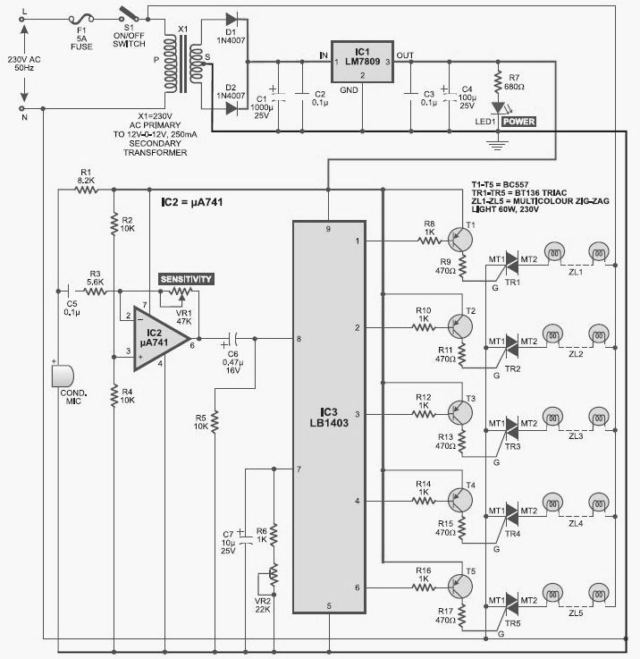
This light chaser circuit, which functions as a music-operated lighting effect generator, consists of five sets of 60W bulbs arranged in a zig-zag configuration. The light chaser circuit is designed to create dynamic lighting effects that synchronize with music, enhancing...
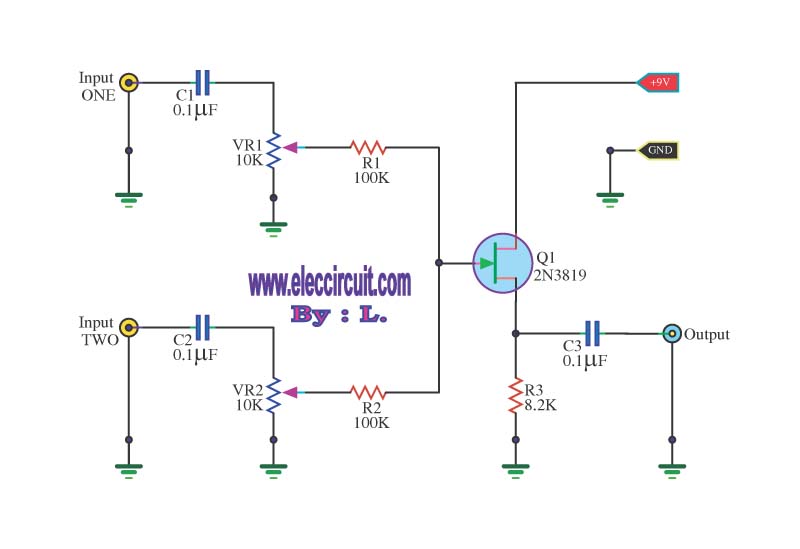
This circuit is a simple mixer circuit that can mix two signal channels into one output channel. It utilizes a codec circuit to convert stereo audio into mono audio. The circuit can also increase the number of channels by...