
The Finder
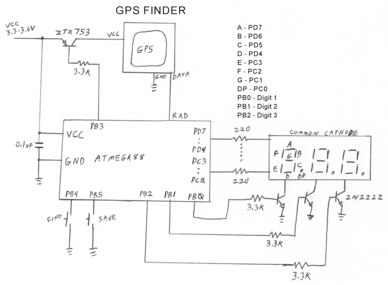
The schematic design for the Finder GPS device is centered around the ATMEGA88 microcontroller, which manages input from the buttons and controls the LED display. The microcontroller interfaces with the GPS module, receiving location data and processing it to determine the user's current position relative to saved locations. The connections between the microcontroller and the GPS module should include power supply lines, ground connections, and data lines for communication. The common cathode LED display is connected to the microcontroller's output pins, allowing it to show the necessary information such as the status of the device, saved locations, and the distance to the target.
Power management is crucial for the operation of the Finder, necessitating the inclusion of a voltage regulator if using batteries with higher voltage outputs. The circuit should also incorporate bypass capacitors near the power pins of the microcontroller and GPS module to ensure stable operation. The button inputs can be configured with pull-up resistors to maintain a defined logic level when the buttons are not pressed.
The use of transistors in the circuit can facilitate the control of the LED display, allowing for multiplexing if necessary to reduce the number of pins required on the microcontroller. Resistor values must be chosen to limit the current through the LEDs, ensuring they operate within safe parameters. The EEPROM storage for location data should be carefully mapped in the microcontroller's memory space, with appropriate routines in the software to read and write to this storage.
Overall, the schematic design should emphasize clarity and modularity, making it easy to troubleshoot and modify as needed. Proper labeling of all connections and components will enhance understanding and facilitate future enhancements or repairs.The Finder is a prototype of that device. It is a keychain-sized GPS device with two buttons, Save and Find. Pressing Save records your current location. Pressing Find visually leads you back to the saved location. Up to 9 locations can be saved. Press the Save button, and the device displays S-1. Pressing Save again steps through the slots up to 9. Pressing Find, while S-# is displayed, saves the current location into the chosen slot. The display blinks slowly until the location is found, then strobes quickly and goes blank, indicating the location is saved. Pressing any button will stop the process and turn the device off. Press the Find button, and the device displays F-1. Pressing Find again steps through the slots up to 9. Pressing Save, while F-# is displayed, navigates you to the chosen location. The display blinks while the GPS finds its position, and then changes to a three-digit distance, in yards or meters (meters constant to be added.
) Start walking forward when the distance appears. One segment of the display will blink, indicating the direction to go. If the top segment of the middle digit blinks, go straight ahead. If segments to the left of center blink, turn left. If segments to the right of center blink, turn right. If one of the bottom segments blinks, turn around. Try to keep the top middle segment blinking. The distance will count down as you approach your destination. When you are done, press either button to turn the device off. The Finder requires an ATMEGA88 or larger, a three-digit, common cathode LED display (Mouser BC56-11EWA or BC56-12GWA), an AARLOGIC GPS 3A or similar GPS module, and a 3. 6 volt battery. A cell phone battery (3. 7V) or three NiMH cells will work. If you use three Alkaline cells, use a series diode to reduce the voltage by 0. 7 volts. Other parts required are four transistors, twelve resistors, a capacitor, and two buttons. The program is about 3500 bytes long. The prototype shown above has all the parts mounted on the back of the display, and sealed with a glue gun.
The flying wires could easily be eliminated. I used thick film resistor packs instead of individual resistors, and wired everything together with 30-gauge rework wire. Other things you should know: If you leave the device in F or S mode without selecting a location, it will turn itself off.
If you try to Find a location and get -, that location has not been saved. Locations are stored in EEPROM on 24-byte boundaries. If the distance is more than 1000 yards/meters, the decimal points indicate the 1000s in binary. If the rightmost decimal is lit and the display says 430, the real distance is 1430. If the leftmost and center decimal are lit, the distance is 6430. How it works: The Finder uses the Great Circle navigation algorithm explained in this Circuit Cellar article Stefan123. pdf by Jeff Stefan. The algorithm takes the From and To LAT/LON pairs, does some arithmetic and trigonometry, and computes a distance and course which are the shortest path on the surface of a sphere.
It then subtracts the current course, indicated by the GPS module, from the computed course, and displays the relative course, which is the direction you should walk. The program uses 64-bit, two`s complement arithmetic. For most of the radians calculations, the first byte is integer and the rest fractional, so divide the binary integer by 256 to get the decimal number.
The Great Circle algorithm requires precision COS and ARCCOS functions. The COS function is a polynomial approximation. The ARCCOS functions I looked at were very complex: one required two polynomials, a square root, and a division. Therefore, my ARCCOS uses Newton`s method to invert the COS function. That is compact but relatively slow, and the algorithm requires about 1. 3 million machine cycles to compute a great circle. The GPS provides one fix per second, and the CPU runs a 🔗 External reference
Related Circuits
Thanks to the S6986, the circuit is very simple and requires few components. D2, D3, D5 and D6 forms a bridge rectifier allowing to plug the sensor connector brick in any direction. C1 filters power supply, it must be...
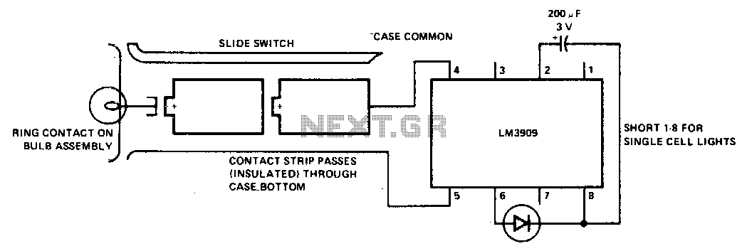
Notes: The LM3909, capacitor, and LED are installed in a white translucent cap on the flashlight's back end. Only one contact strip (in addition to the case connection) is needed for flasher power. More: Drawing current through the bulb...
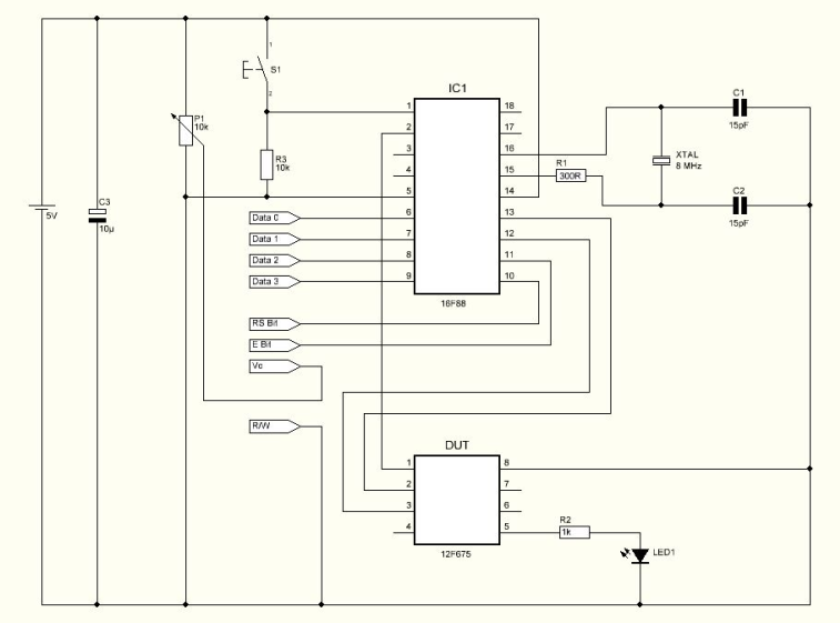
The program loaded in the 12F675 device which has no osccal value will force a pulse on GPIO.4 and it will make a loop while increasing the osccal value internally. GPIO.5 will send the current osccal value used for...
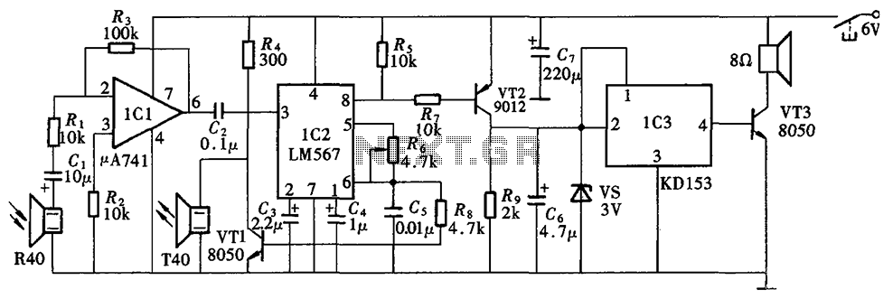
The Blind Pathfinder circuit primarily consists of the A741 operational amplifier, LM567 phase-locked loop, KD153 transistor, 8050 transistor, 9012 transistor, and various other components. The Blind Pathfinder circuit is designed to assist in navigation and obstacle detection, typically utilized in...

A 2008 USA Nissan Pathfinder (VIN: 5N1AR18B28C628086) is experiencing issues with the power-assisted mechanism for closing the lift gate (trunk, rear door). The problem began approximately two months ago. The vehicle was taken to Willowdale Nissan in Thornhill, Ontario,...
The block diagram illustrating the device and operation of the sonic depth finder is depicted in Figure 1. The clock generator G1 facilitates the interaction of the device's components, enabling automatic functionality. It generates short rectangular pulses of positive...